Brake Pedal Assy: Service and Repair
Brake Pedal and BracketBrake Pedal and Bracket:
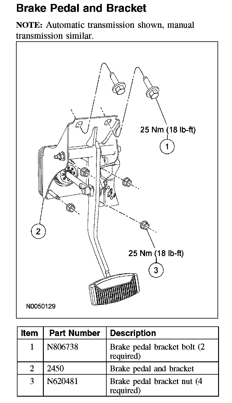
Removal and Installation
All vehicles
1. Disconnect the battery ground cable. For additional information, refer to Battery.
2. CAUTION: Always remove the stoplamp switch before removing the speed control deactivator switch. Always remove both switches with the brake pedal secured to the brake booster push rod and with the brake pedal in the at-rest position.Do not press or pull on the brake pedal when removing the switches or damage to the switches can occur.
CAUTION: The stoplamp switch and the speed control deactivator switch must be removed prior to removing the brake pedal and bracket, and the brake booster and associated mounting fasteners or damage to the switches can occur.
Remove the stoplamp switch. For additional information, refer to Lighting and Horns.
3. If equipped, remove the speed control deactivator switch. For additional information, refer to Cruise Control.
Manual transmission
4. Disconnect the clutch pedal position (CPP) switch.
5. NOTE: The clutch pedal master cylinder push rod retaining clip is not reusable.
Disconnect the clutch pedal master cylinder push rod.
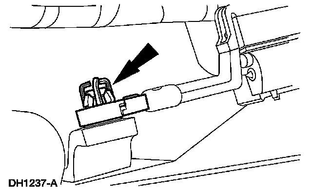
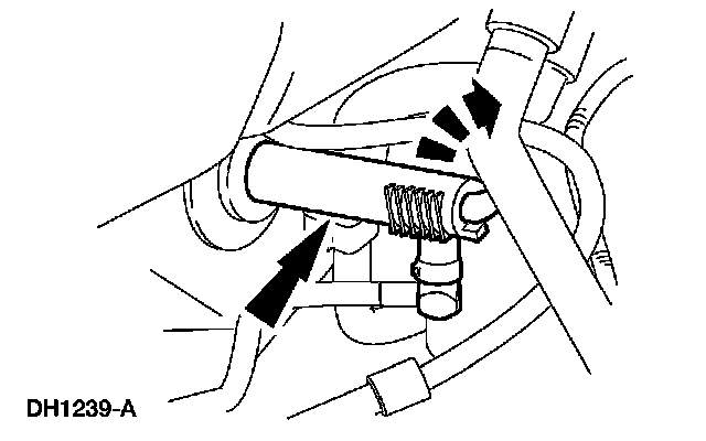
6. Remove the clutch master cylinder from the brake and clutch pedal bracket by rotating it 45 degrees clockwise.
All vehicles
7. Remove the bulkhead sound insulator.
8. Remove the 2 brake pedal bracket bolts.
^ To install, tighten to 25 Nm (18 ft. lbs).
9. CAUTION: Support the brake master cylinder and power brake booster in the engine compartment.
Remove the 4 brake pedal bracket nuts and remove the brake pedal and bracket.
^ To install, tighten to 25 Nm (18 ft. lbs).
10. CAUTION: Do not install the stoplamp switch and the speed control deactivator switch until installation of the brake booster, and the brake pedal and bracket are complete. The brake pedal arm must be secured to the brake booster push rod and in the at-rest position prior to switch installation. Failure to follow these instructions can result in incorrect adjustment or damage to the switches.
CAUTION: Do not press, pull or otherwise move the brake pedal while installing the stoplamp switch or the speed control deactivator switch. Failure to follow these instructions can result in incorrect adjustment or damage to the switches.
To install, reverse the removal procedure.