Removal and Replacement
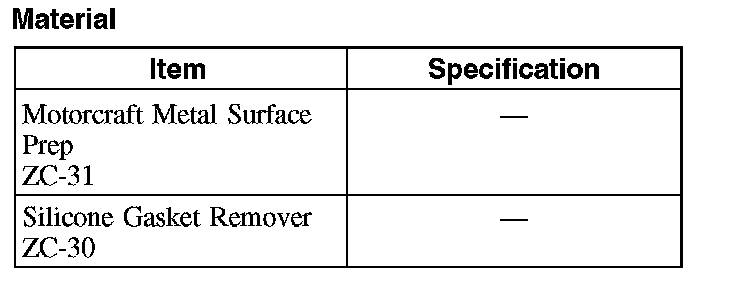
Intake ManifoldMaterial:
Electrical, Tube and Hose Connections (Part 1):
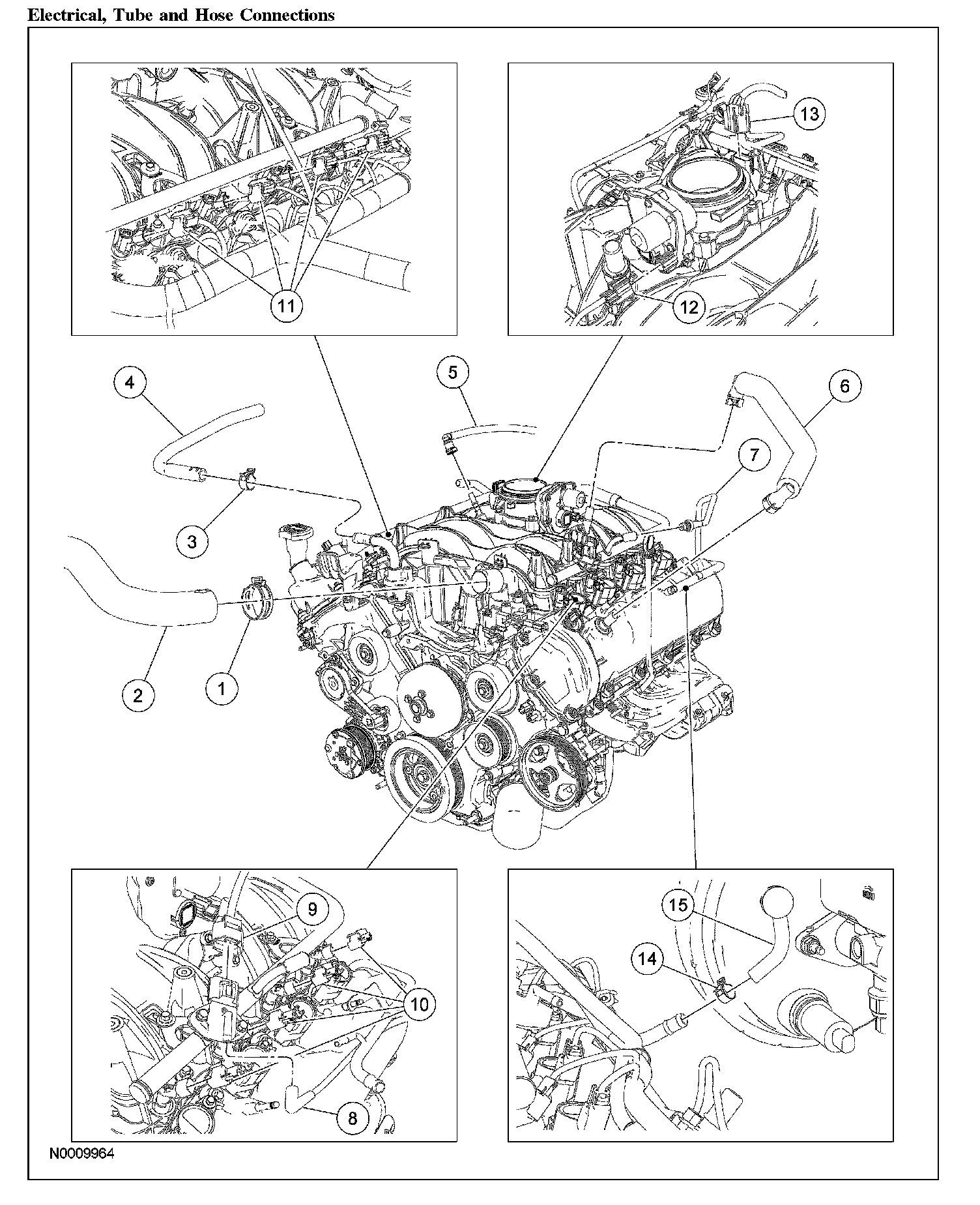
Electrical, Tube and Hose Connections (Part 2):
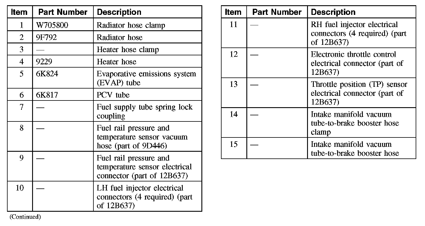
Intake Manifold and Engine Coolant Crossover Assembly (Part 1):
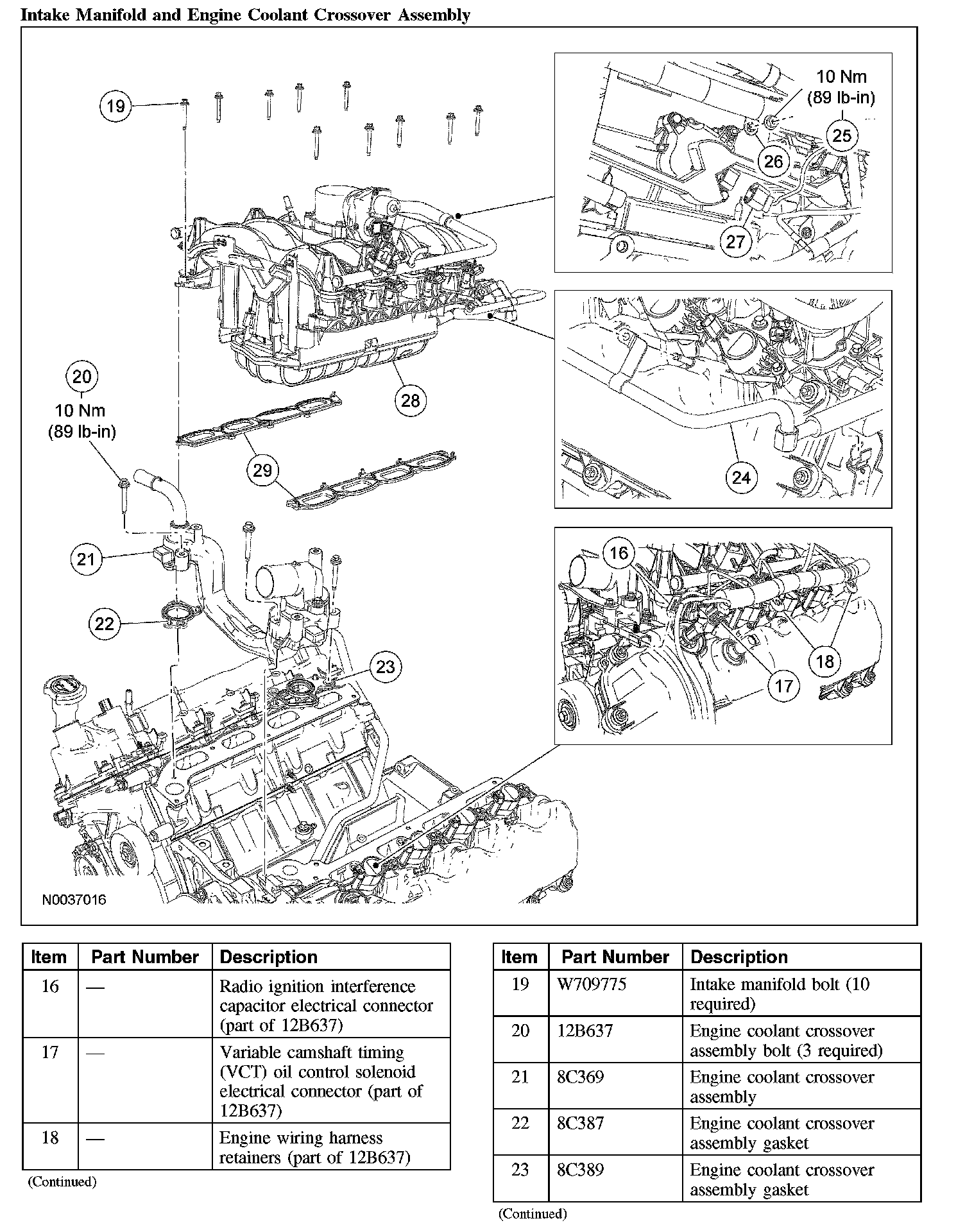
Intake Manifold and Engine Coolant Crossover Assembly (Part 2):
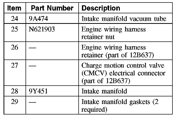
Removal
WARNING: Do not smoke, carry lighted tobacco or have an open flame of any type when working on or near any fuel related component. Highly flammable mixtures are always present and may be ignited. Failure to follow these instructions may result in serious personal injury.
WARNING: Before working on or disconnecting any of the fuel tubes or fuel system components, relieve the fuel system pressure to prevent accidental spraying of fuel. Fuel in the fuel system remains under high pressure, even when the engine is not running. Failure to follow this instruction may result in serious personal injury.
1. Disconnect the fuel supply tube spring lock coupling. For additional information, refer to Fuel Delivery and Air Induction.
2. Drain the cooling system. For additional information, refer to Cooling System.
3. Remove the generator. For additional information, refer to Alternator.
4. Remove the air cleaner. For additional information, refer to Fuel Delivery and Air Induction.
5. Disconnect the upper radiator hose from the thermostat housing.
6. Disconnect the heater coolant hose from the coolant bypass tube.
7. Disconnect the quick connect coupling and remove the evaporative emissions (EVAP) tube from the intake manifold. For additional information, refer to Fuel Delivery and Air Induction.
8. Disconnect the fuel rail pressure and temperature sensor electrical connector and vacuum connector.
9. Disconnect the 8 fuel injector electrical connectors.
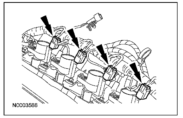
10. Disconnect the 4 LH ignition coil electrical connectors.
11. Disconnect the throttle position (TP) sensor and electronic throttle control electrical connectors.
12. Disconnect the heated PCV element electrical connector.
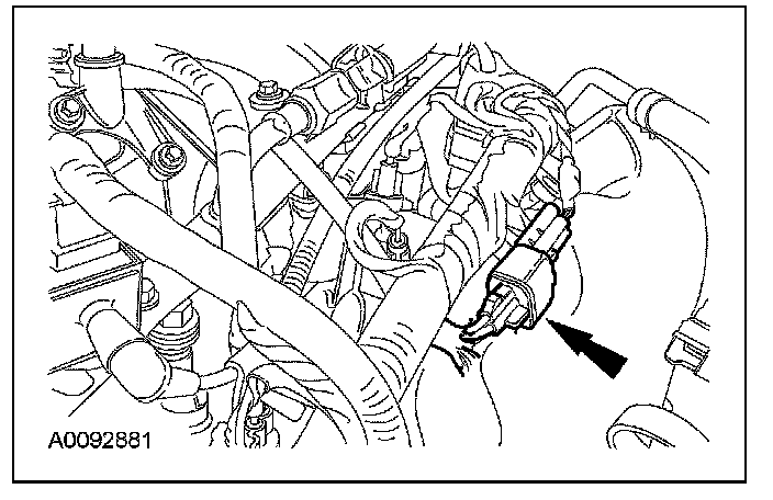
13. Disconnect the engine oil pressure (EOP) sensor electrical connector.
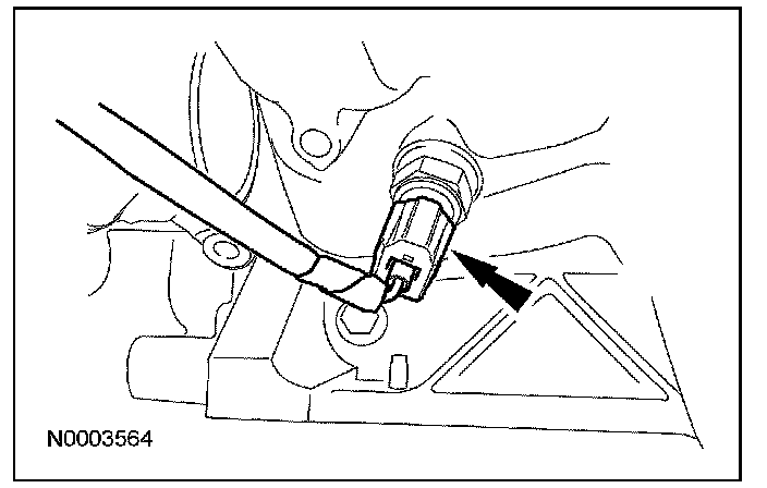
14. Disconnect the LH camshaft position (CMP) sensor electrical connector.
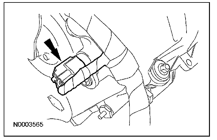
15. Disconnect the LH variable camshaft timing (VCT) solenoid electrical connector.
16. Disconnect the LH radio ignition interference capacitor electrical connector.
17. Disconnect the wiring harness retainers from the LH valve cover studs and position the harness aside.
18. Disconnect the brake booster vacuum hose from the intake manifold vacuum tube.
19. Remove the 10 intake manifold bolts.
20. CAUTION: Do not use metal scrapers, wire brushes, power abrasive discs or other abrasive means to clean the sealing surfaces. These tools cause scratches and gouges which make leak paths. Use a plastic scraping tool to remove all traces of old sealant.
Remove the 3 bolts, the coolant bypass tube and discard the gaskets.
^ Clean and inspect the sealing surfaces with silicone gasket remover and metal surface prep. Follow the directions on the packaging.
21. Disconnect the charge motion control valve (CMCV) electrical connector.
22. Disconnect the intake manifold vacuum tube from the valve cover stud and the support bracket.
23. Position the intake manifold assembly forward and disconnect the cylinder head temperature (CHT) sensor jumper harness electrical connector.
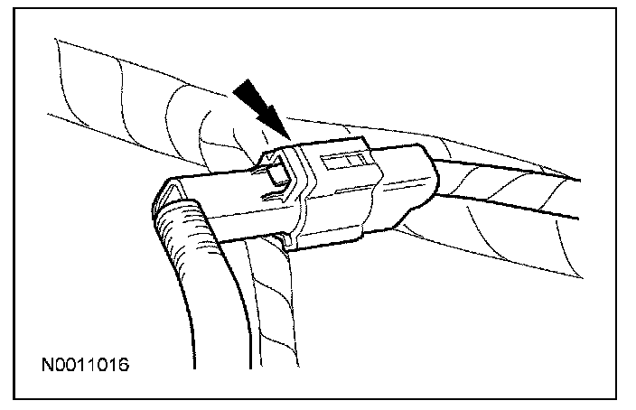
24. Disconnect the LH and RH knock sensor (KS) electrical connectors.
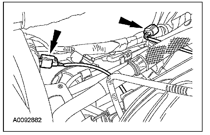
25. Remove the nut and disconnect the engine wiring harness retainer from the CMCV stud.
26. Disconnect the RH heated exhaust gas oxygen sensor (HO2S) electrical connector and detach the electrical connector retainer.
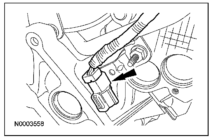
27. CAUTION: Do not use metal scrapers, wire brushes, power abrasive discs or other abrasive means to clean the sealing surfaces. These tools cause scratches and gouges which make leak paths. Use a plastic scraping tool to remove all traces of old sealant.
Remove the intake manifold and discard the gaskets.
^ Clean and inspect the sealing surfaces with silicone gasket remover and metal surface prep. Follow the directions on the packaging.
Installation
1. NOTE: Electrical and vacuum harnesses must not restrict movement of the CMCV control rods at the rear of the intake manifold. Use extreme care on installation of the intake manifold to prevent any pinching of electrical and vacuum harnesses.
Using new intake manifold gaskets, position the intake manifold.
2. Using new gaskets, position the coolant crossover and install the 3 bolts.
^ Tighten to 10 Nm (89 lb-in).
3. Install the intake manifold bolts and tighten in 2 stages in the sequence shown.
^ Stage 1: Tighten to 2 Nm (18 lb-in).
^ Stage 2: Tighten to 10 Nm (89 lb-in).

4. Connect the HO2S electrical connector and attach the electrical connector assembly to the retaining bracket.
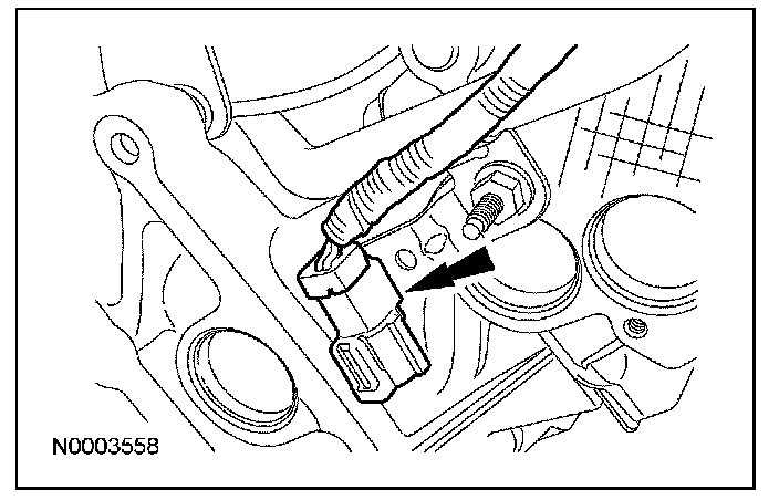
5. Connect the engine wiring harness retainer to the CMCV stud and install the nut.
^ Tighten to 10 Nm (89 lb-in).
6. Connect the CMCV electrical connector.
7. Connect the CHT sensor jumper harness electrical connector.
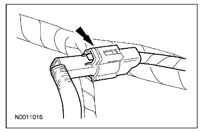
8. Connect the LH and RH KS electrical connectors.
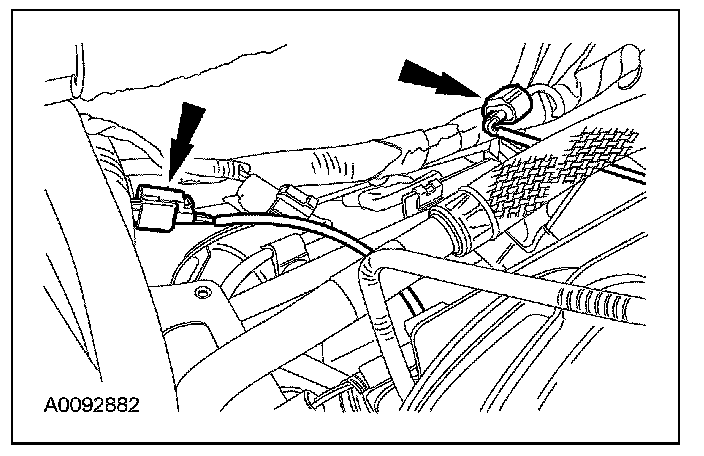
9. Connect the intake manifold vacuum tube to the support bracket and the valve cover stud.
10. Connect the brake booster vacuum hose to the intake manifold vacuum tube.
11. Position the engine wiring harness and connect the wiring harness retainers to the LH valve cover stud bolts.
12. Connect the LH radio ignition interference capacitor electrical connector.
13. Connect the LH VCT solenoid electrical connector.
14. Connect the LH CMP sensor electrical connector.
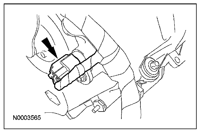
15. Connect the EOP sensor electrical connector.
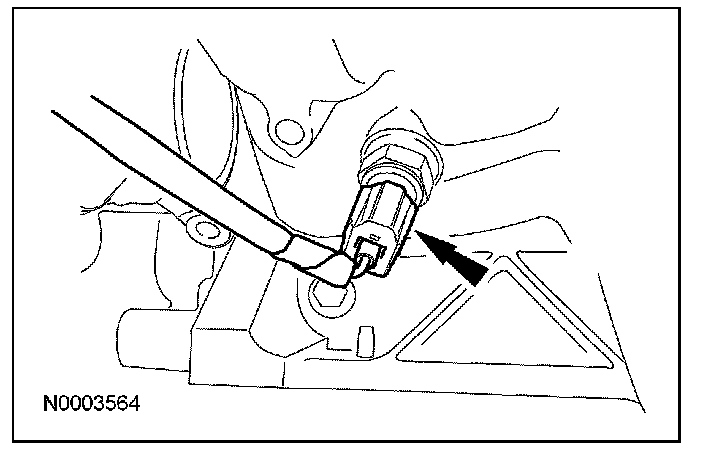
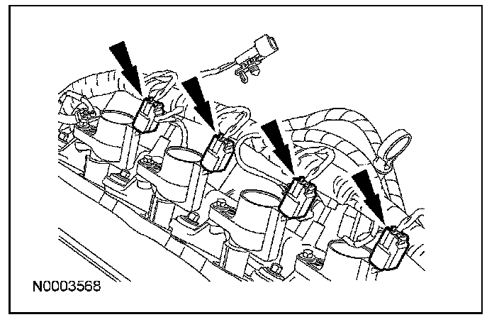
16. Connect the 4 LH ignition coil electrical connectors.
17. Connect the heated PCV element electrical connector.
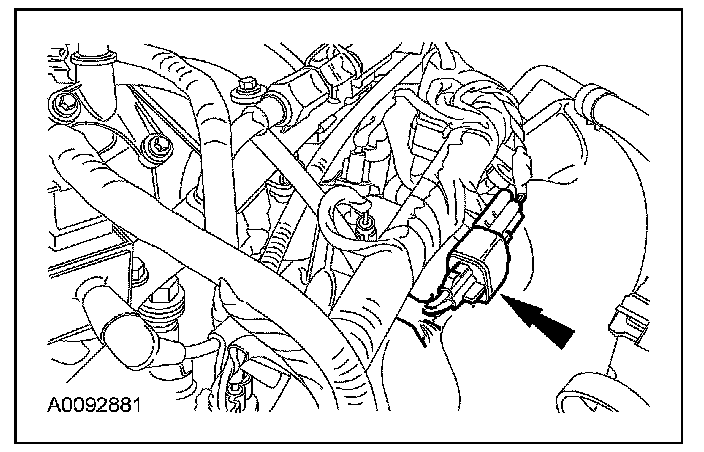
18. Connect the TP sensor and electronic throttle control electrical connectors.
19. Connect the 8 fuel injector electrical connectors.
20. Connect the fuel rail pressure and temperature sensor electrical connector and vacuum connector.
21. Connect the fuel supply tube spring lock coupling to the fuel rail.
22. Position the PCV tube and connect the quick connect coupling.
23. Position the EVAP tube and connect the quick connect coupling to the intake manifold.
24. Connect the heater coolant hose to the coolant bypass.
25. Connect the upper radiator hose to the thermostat housing.
26. Install the generator.
27. Install the air cleaner.
28. Fill and bleed the engine cooling system.