Removal and Replacement
SEAT BACKREST - FRONTExploded View
Front Seat Backrest - With Seat Integrated Restraints (SIR):

Front Seat Backrest - Without Seat Integrated Restraints (SIR):

Front Seat Cushion - Driver (Part 1):

Front Seat Cushion - Driver (Part 2):

Front Seat Cushion - Passenger (Part 1):

Front Seat Cushion - Passenger (Part 2):

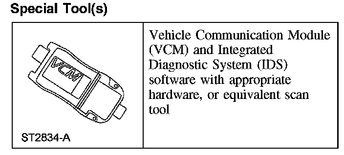
Special Tool(s)
Special Tool(s):
Removal and Installation
WARNING: Never probe the electrical connectors on safety belt buckle/retractor pretensioners or adaptive load limiting retractors. Failure to follow this instruction may result in the accidental deployment of the safety belt pretensioners or adaptive load limiting retractors, which increases the risk of serious personal injury or death.
CAUTION: It is necessary to carry out the occupant classification sensor (OCS) system reset when a front passenger seat cushion is disassembled, a new trim cover is installed or an OCS system service kit is installed. A scan tool is used to carry out the OCS system reset command. Failure to follow this instruction may result in system failure and the incorrect operation of the OCS system.
NOTE:
- The air bag warning indicator illuminates when the restraints control module (RCM) fuse is removed and the ignition switch is ON. This is normal operation and does not indicate a supplemental restraint system (SRS) fault.
- The SRS must be fully operational and free of faults before releasing the vehicle to the customer.
- Power seat shown, manual seat similar.
All seats
1. Remove the seat.
2. If equipped, disconnect the seat control switch electrical connector.
3. NOTE: To aid cushion removal, position the backrest rearward before removing the recliner handle.
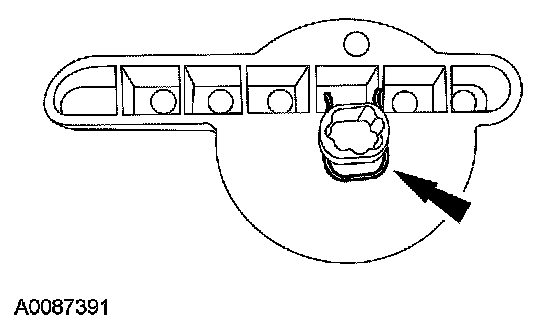
Remove the recliner handle.
- Release the clip at the rear of side shield by detaching the clip from the metal bracket on the track. Partially flex the side shield at the rear to obtain access to the recliner handle clip. Remove the recliner handle clip (shown removed for clarity) and the recliner handle.
4. If equipped, adjust the lumbar until fully relaxed and remove the lumbar knob.
5. Remove the side shield control panel.
6. If equipped, disconnect the memory SET switch electrical connector.
7. Release the pin-type retainer at the front of the side shield.
8. Remove the 3 screws and side shield.
9. CAUTION: To prevent component damage and avoid setting diagnostic trouble codes (DTCs), the following precautions must be taken:
- The position assurance locking wedge must be in the released position when inserting or removing the electrical connector from the safety belt buckle and pretensioner.
- Do not install the electrical connector by pushing on the position assurance locking wedge.
- Make sure the electrical connector and position assurance locking wedge are fully seated after connecting to the safety belt buckle and pretensioner.
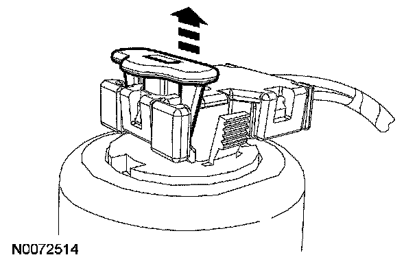
Release the locking wedge on the safety belt buckle and pretensioner electrical connector.
10. NOTE: If equipped with manual lumbar, make sure the wire harness is routed above the manual lumbar cable.
Disconnect the safety belt buckle and pretensioner electrical connector.
11. Disconnect the safety belt buckle switch electrical connector.
12. If equipped, disconnect the backrest heater mat electrical connector.
Seat with seat integrated restraints (SIR)
13. Remove the safety belt anchor nut.
- To install, tighten to 55 Nm (41 lb-ft).
- If passenger seat, disconnect the belt tension sensor (BTS) electrical connector.
All seats
14. If equipped, disconnect the power seat track electrical connector and release any pin-type retainers attached to the seat cushion frame.
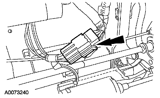
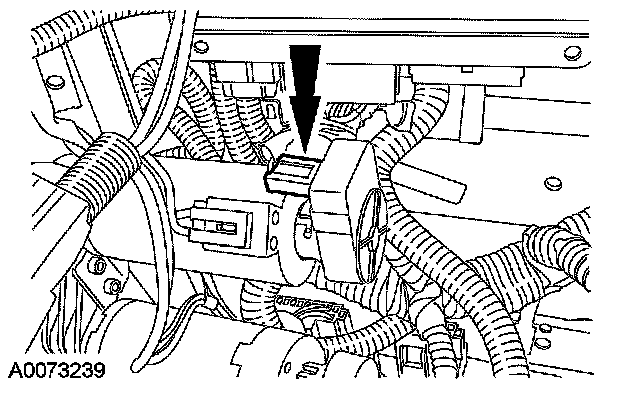
15. If equipped, disconnect the 3 memory seat position sensor electrical connectors (one shown) and detach the wiring harness from the cushion frame.
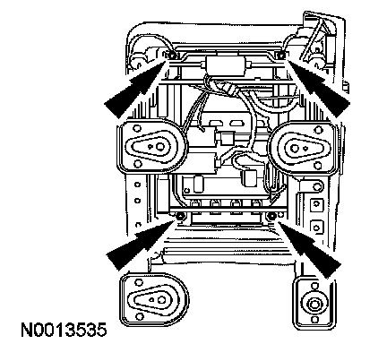
16. Remove the 4 nuts and cushion frame.
- To install, tighten to 25 Nm (18 lb-ft).
- Disconnect and detach any remaining electrical connectors and wire harness attached to the seat cushion frame.
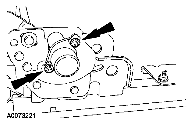
17. Remove the 2 screws and lumbar adjuster.
18. NOTE:
- The lumbar assembly should be fully relaxed before cable disconnection.
- Note cable routing for installation.
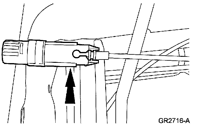
Detach the lumbar cable from the lumbar adjuster and route through the seat.
19. Remove the outboard recliner front bolt and screw.
1 To install, tighten to 35 Nm (26 lb-ft).
2 To install, tighten to 10 Nm (89 lb-in).
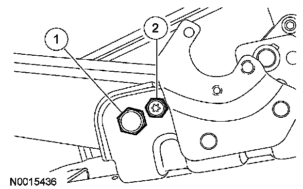
20. Remove the inboard recliner front bolt.
- To install, tighten to 35 Nm (26 lb-ft).
21. NOTE: Do not damage the plastic pivot bushing when removing or installing the backrest pivot bolt.
Remove the inboard backrest pivot bolt.
- To install, tighten to 35 Nm (26 lb-ft).
22. Remove the outboard backrest pivot bolt and remove the backrest.
- To install, tighten to 40 Nm (30 lb-ft).
23. To install, reverse the removal procedure.
- Make sure the safety belts and buckles are accessible to the occupants after installation.
- Verify the safety belt retractor operates without excessive effort or binding.
24. Install the seat. If a passenger seat has been serviced, do not prove out the SRS at this time.
Passenger seat
25. WARNING:
- Install a new occupant classification sensor (OCS) system service kit as a complete assembly. Never install only part of the kit components. Failure to follow this instruction may result in incorrect operation of the OCS system and increases the risk of serious personal injury or death in a crash.
- Make sure the front passenger seat repair is complete, the seat and all attached components (head restraint, seat side shield, etc.) are correctly assembled, and the seat is correctly installed to the vehicle before carrying out the System Reset. Failure to follow these instructions may result in incorrect operation of the occupant classification sensor (OCS) system and increases the risk of serious personal injury or death in a crash.
CAUTION:
- It is necessary to carry out the occupant classification sensor (OCS) system reset when a front passenger seat cushion is disassembled, a new trim cover is installed or an OCS system service kit is installed. A scan tool is used to carry out the OCS system reset command. Failure to follow this instruction may result in system failure and the incorrect operation of the OCS system.
- To prevent system failure, the following precautions must be taken before carrying out the occupant classification sensor (OCS) system reset:
- Make sure the voltage to the occupant classification system module (OCSM) is above 8.0 volts and less than 18.0 volts.
- Make sure the OCS system is not at a temperature below 6°C (42°F) or above 36°C (97°F) when initiating the OCS system reset process. If the vehicle has been exposed to extreme cold or hot temperatures, the vehicle must be exposed and kept at a temperature within the limits, 6°C to 36°C (42°F to 97°F) for a minimum of 30 minutes.
- Make sure nothing is present on the passenger seat before carrying out the OCS system reset and nothing is placed on the seat during the process.
- Make sure a minimum 8-second time period has passed after cycling the ignition switch ON before the carrying out the OCS system reset process.
NOTE: If the first attempt to carry out the OCS system reset is unsuccessful, a second attempt must be made. If the second attempt to carry out the OCS system reset is unsuccessful, a new OCS system service kit must be installed.
Carry out the OCS system reset command using the scan tool.
26. Cycle the ignition switch from ON to OFF.
27. NOTE: The ignition switch must be cycled after the OCS system reset.
Cycle the ignition switch from OFF to ON.
All seats
28. Prove out the SRS as follows:
Turn the ignition key from ON to OFF. Wait 10 seconds, then turn the key back to ON and visually monitor the air bag warning indicator with the air bag modules installed. The air bag warning indicator will light continuously for approximately 6 seconds and then turn off. If an air bag SRS fault is present, the air bag warning indicator will:
- fail to light.
- remain lit continuously.
- flash at a 5Hz rate (RCM not configured).
The air bag warning indicator might not light until approximately 30 seconds after the ignition switch has been turned from the OFF to the ON position. This is the time required for the RCM to complete the testing of the SRS. If the air bag warning indicator is inoperative and a SRS fault exists, a chime will sound in a pattern of 5 sets of 5 beeps. If this occurs, the air bag warning indicator and any SRS fault discovered must be diagnosed and repaired.
Clear all continuous DTCs from the RCM using a scan tool.