Air Conditioning
AIR CONDITIONINGThe A/C refrigerant system is a clutch cycling orifice tube type. The system components are the following:
- A/C compressor
- A/C condenser core
- A/C evaporator core
- Suction accumulator
- Connecting refrigerant lines
The refrigeration system operation is controlled by the following:
- Evaporator core orifice tube
- A/C cycling switch
- A/C compressor pressure relief valve
- A/C pressure transducer
The refrigerant system incorporates an A/C compressor controlled by the PCM through an A/C clutch relay.
The A/C cycling switch senses evaporator core pressure to control A/C compressor operation.
An evaporator core orifice tube is installed in the condenser-to-evaporator line at the A/C condenser fitting to meter the liquid refrigerant into the evaporator core.
The A/C compressor clutch will only be engaged by the PCM if all of the following conditions are met:
- The HVAC module is set to a mode which provides an A/C request to the instrument cluster. This request is then transferred to the PCM through the high-speed controller area network (HS-CAN) bus
- The A/C cycling switch is reading an acceptable low-side refrigerant pressure
- The A/C pressure transducer is reading an acceptable high-side refrigerant pressure
- The A/C compressor relay is energized by the PCM
- The engine coolant temperature is not excessively high
- The PCM has not detected a wide open throttle (WOT) condition
An A/C compressor pressure relief valve is installed in the A/C compressor to protect the refrigerant system against excessively high refrigerant pressures.
A/C Compressor And Clutch Assembly
NOTE: Internal FS20 A/C compressor components are not serviced separately. The A/C compressor is serviced only as an assembly. The clutch disc and hub, A/C compressor pulley and bearing and the clutch field coil are serviceable.
The FS20 A/C compressor uses the following:
- A non-serviceable shaft seal
- A pressure relief valve installed in the rear of the compressor to protect the refrigerant system against excessively high refrigerant pressures
- PAG oil or equivalent. This oil contains special additives required for the A/C compressor
- PAG oil may have some slightly dark-colored streaks while maintaining normal oil viscosity. This is normal for this A/C compressor because of break-in wear that can discolor the oil.
Use standard oil matching procedures when installing new compressors.
A/C Compressor Clutch Assembly:

The magnetic A/C clutch has the following characteristics:
- The A/C clutch drives the compressor shaft
- When battery positive voltage (B+) is applied to the A/C clutch field coil, the clutch disc and hub assembly is drawn toward the A/C clutch pulley
- The magnetic force locks the clutch disc and hub assembly and the A/C clutch pulley together as one unit, causing the compressor shaft to rotate
- When B+ is removed from the A/C clutch field coil, springs in the clutch disc and hub assembly move the clutch disc away from the A/C clutch pulley
A/C Pressure Relief Valve
NOTE: If the A/C compressor is operating within limits and the A/C pressure relief valve is venting, or if the A/C pressure relief valve is leaking around the threads, replace the A/C pressure relief valve and O-ring seal. If the A/C pressure relief valve still vents after it is replaced, diagnose the refrigerant system for a restriction.
An A/C pressure relief valve is incorporated in the A/C compressor to prevent damage to the A/C compressor and other system components by relieving unusually high system discharge pressure buildups.
The A/C pressure relief valve is a separate component and can be replaced separately from the A/C compressor. It is necessary to recover the refrigerant before removing the A/C pressure relief valve.
Condenser Core
The condenser core has the following characteristics:
- It is an aluminum fin and tube design heat exchanger located in front of the vehicle radiator
- It cools compressed refrigerant gas by allowing air to pass over fins and tubes to extract heat and by condensing gas to liquid refrigerant as it is cooled
Evaporator Core
NOTE: If an evaporator core leak is suspected, the evaporator core must be vacuum leak tested before it is removed from the vehicle.
The evaporator core is a plate/fin type.
- A mixture of refrigerant and oil enters the bottom of the evaporator core through the evaporator core inlet tube and then moves out of the evaporator core through the evaporator core outlet tube.
- Airflow from the blower motor passes through the evaporator core where it is cooled and dehumidified before entering the passenger compartment.
Evaporator Core Orifice Tube
NOTE: A new evaporator core orifice tube should be installed whenever a new A/C compressor is installed.
The A/C evaporator core orifice has the following characteristics:
- It is located in the condenser-to-evaporator line at the condenser fitting
- It has filter screens located on the inlet and outlet ends of the tube body
- The inlet filter screen acts as a strainer for the liquid refrigerant flowing through the evaporator core orifice tube
- O-ring seals on the evaporator core orifice tube prevent the high-pressure liquid refrigerant from bypassing the evaporator core orifice tube
- Adjustment or service cannot be carried out to the evaporator core orifice tube. A new evaporator core orifice must be installed
Suction Accumulator
NOTE: Installation of a new suction accumulator is not required when repairing the A/C system, except when there is physical evidence of contamination from a failed A/C compressor or damage to the suction accumulator. Damage to the suction accumulator includes leaks in the suction accumulator, physical damage to the suction accumulator shell or desiccant, or moisture contamination. Moisture contamination results only from a complete loss of refrigerant and equalization of the refrigerant system pressure with atmospheric pressure for a period longer than one hour. If even a slight amount of positive refrigerant pressure is present in the system before repairs are carried out, the suction accumulator should not be replaced.
The suction accumulator is mounted at the RH rear of the engine compartment. The evaporator outlet line attaches directly to the inlet of the suction accumulator and the compressor manifold and tube assembly attaches to the suction accumulator outlet.
After entering the inlet of the suction accumulator, the heavier oil-laden refrigerant contacts an internally mounted dome (which serves as an umbrella) and drips down onto the bottom of the canister.
- A small diameter oil bleed hole, in the bottom of the vapor return tube, allows the accumulated heavier liquid refrigerant and oil mixture to re-enter the compressor suction line at a controlled rate.
- As the heavier mixture passes through the small diameter liquid bleed hole, it has a second chance to vaporize and recirculate through the A/C compressor without causing compressor damage due to slugging.
- A fine mesh screened filter fits tightly around the bottom of the vapor return inlet to filter out refrigerant system contaminant particles.
- A desiccant bag is mounted inside the canister to absorb any moisture which may be in the refrigerant system.
A/C Cycling Switch
The A/C cycling switch is mounted on a Schrader valve-type fitting on the suction accumulator.
- A valve depressor, located inside the threaded end of the A/C cycling switch, presses in on the Schrader valve stem.
- This allows the suction pressure to control the operation of the A/C cycling switch.
- Battery voltage is present at one side of the A/C cycling switch at all times when the ignition switch is in the RUN position.
- When the switch contacts are closed, the battery voltage circuit is completed to the PCM to signal that the low-side refrigerant system pressure is acceptable for A/C compressor operation.
- When the switch contacts are open, the battery voltage circuit is opened to signal the PCM that the low-side refrigerant system pressure is too low for A/C compressor operation.
- The A/C cycling switch will control the evaporator core pressure at a point where the plate/fin surface temperature will be maintained slightly above freezing.
- This prevents icing of the evaporator core and blockage of airflow.
- It is not necessary to recover the refrigerant to remove the A/C cycling switch.
A/C Pressure Transducer
The A/C pressure transducer communicates the compressor discharge pressure to the PCM. The PCM will interrupt A/C compressor operation in the event that the A/C pressure transducer indicates excessively high system discharge pressures. It is also used to sense low charge conditions. If the pressure is below a predetermined value for a given ambient temperature, the PCM will not allow the clutch to engage.
Spring Lock Coupling
Spring Lock Coupling:
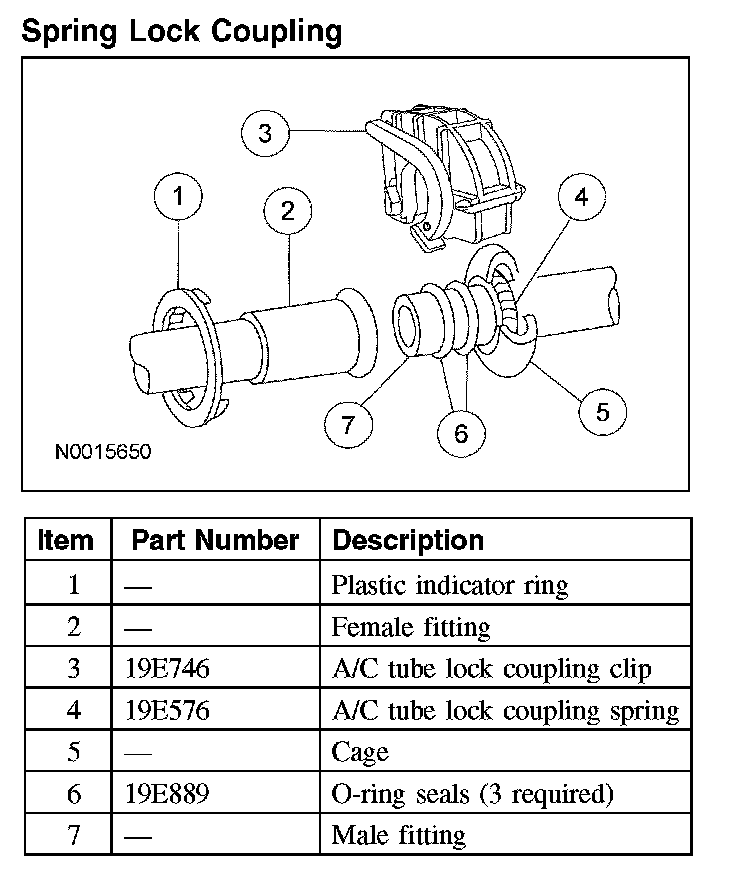
When disconnecting or connecting spring lock couplings, observe the following.
- When the coupling is connected together, the flared end of the female fitting slips behind the garter spring inside the cage of the male fitting.
- The garter spring and cage then prevent the flared end of the female fitting from pulling out of the cage.
- Three O-ring seals are used to seal between the 2 halves of the couplings.
- Use only the O-ring seals listed in the Ford Master Parts Catalog for the spring lock coupling.
- A plastic indicator ring is used to indicate, during vehicle assembly, that the coupling is connected. Once the coupling is connected, the indicator ring is no longer necessary but will remain captive by the coupling near the cage opening.
- The indicator ring may also be used during service operations to indicate connection of the coupling.
- An A/C tube lock coupling clip may be used to secure the coupling but is not required.
Service Gauge Port Valves
The high-pressure service gauge port valve is located on the compressor-to-condenser discharge line.
The low-pressure service gauge port valve is located on the suction accumulator-to-compressor line.
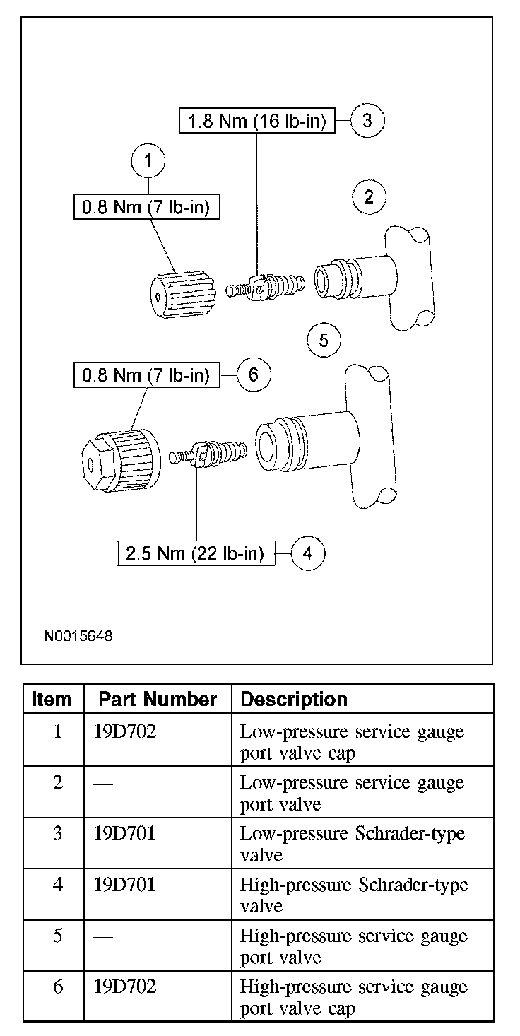
The fitting is an integral part of the refrigeration line or component.
- Special couplings are required for both the high-side and low-side service gauge ports.
- A very small amount of leakage will always be detectable around the Schrader-type valve with the service gauge port valve cap removed and is considered normal. A new Schrader-type valve core can be installed if the seal leaks excessively.
- The service gauge port valve caps are used as primary seals in the refrigerant system to prevent leakage through the Schrader-type valves from reaching the atmosphere. Always install and tighten the A/C service gauge port valve caps to the correct torque after they are removed.
Refrigerant System Dye
Fluorescent refrigerant system dye is added to the refrigerant system at the factory to assist in refrigerant system leak diagnosis using a Rotunda-approved ultraviolet blacklight. It is not necessary to add additional dye to the refrigerant system before diagnosing leaks, even if a significant amount of refrigerant has been removed from the system. New suction accumulators are shipped with a fluorescent dye "wafer" included in the desiccant bag, which will dissolve after approximately 30 minutes of continued A/C operation. It is not necessary to add dye after flushing or filtering the refrigerant system because a new suction accumulator is installed as part of the flushing or filtering procedure. Additional refrigerant system dye should only be added if more than 50 percent of the refrigerant system lubricant capacity has been lost due to a fitting separation, hose rupture or other damage.