Test E: When the Ignition Key Is Turned to the RUN Position the TBC Module Display Does Light Up/Prove Out and the Trailer Brak
Pinpoint Test E: When the Ignition Key is Turned to the RUN Position, the TBC Module Display Does Light Up/Prove Out and the Trailer Brakes are InoperativeNOTE: Carry out all pinpoint tests without a trailer connected to the vehicle.
Refer to Vehicle/Diagrams, Trailer/Camper Adapter for schematic and connector information.
Normal Operation
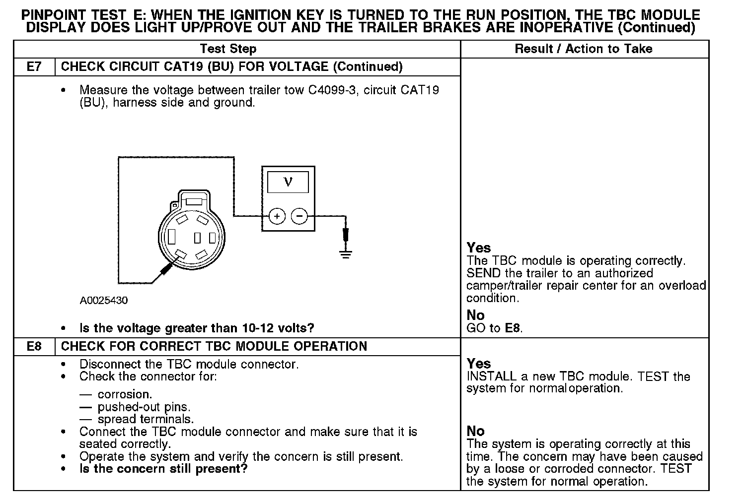
The braking energy that is provided to the trailer is varied with a pulse width modulated (PWM) signal along circuit CAT19 (BU) that switches between 0 volt and battery voltage, the higher the duty cycle the more braking power available. The trailer brake control (TBC) module varies the PWM signal based on various inputs such as the brake pressure transducer, TBC module manual slider switch and the TBC module gain buttons. With the vehicle stationary and with the manual slider switch fully to the left with a gain of 10, there should be greater than 10-12 volts supplied to trailer tow C4099-3 circuit CAT19 (BU).
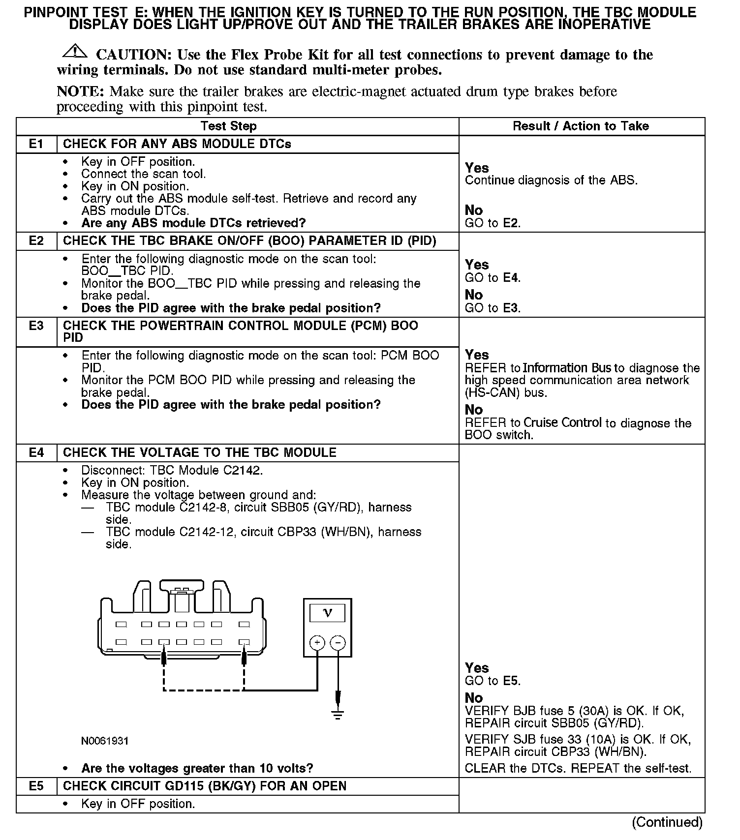
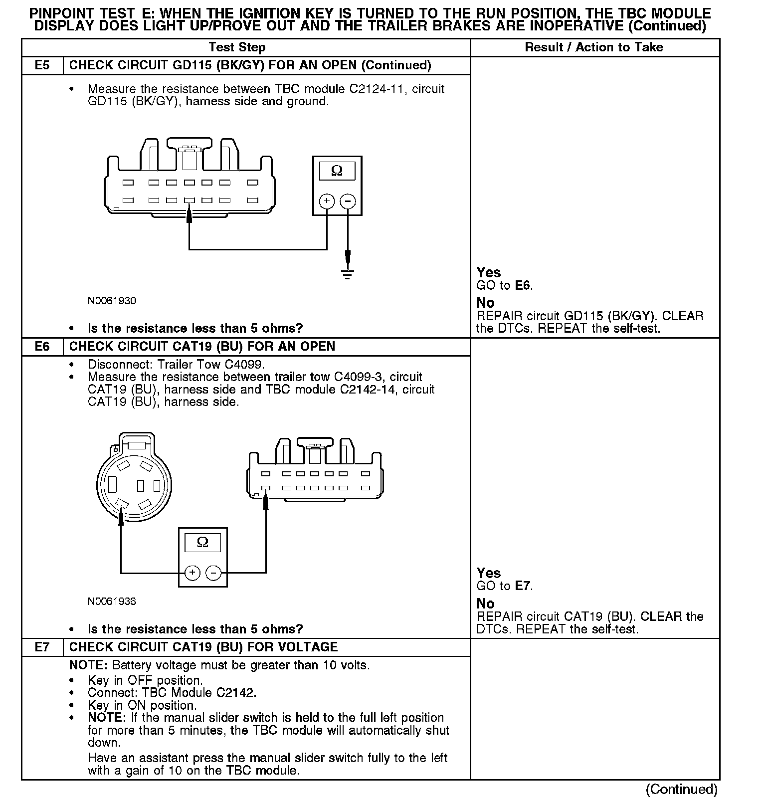
The TBC module receives information from the ABS module along the high speed communication area network (HS-CAN) bus. If there is a problem in the ABS module that is preventing this information from being sent to the TBC module, the TBC module will enter a limited operating mode. The TBC module receives fused battery voltage from battery junction box (BJB) fuse 5 (30A) along circuit SBB05 (GY/RD) and fused ignition voltage from smart junction box (SJB) fuse 33 (10A) along circuit CBP33 (WH/BN). The ground path for the TBC module is along circuit GD115 (BK/GY).
This pinpoint test is intended to diagnose the following:
^ Fuse(s)
^ Wiring, terminals or connectors
^ ABS module
^ TBC module
^ Customer trailer
E1-E5:
E5 (Continued)-E7:
E7 (Continued)-E8: