F1-F20
Air Bag and Safety Belt Pretensioner Supplemental Restraint System (SRS)
Pinpoint Tests
Pinpoint Test F: DTC B2290
Refer to Wiring Diagram Set 46, Supplemental Restraint System for schematic and connector information. Diagrams By Number
NOTE: DTC B2290 reported by the Restraints Control Module (RCM) is informational only and indicates the presence of a fault in the Occupant Classification System Module (OCSM).
NOTE: The following pinpoint test must only be used to diagnose DTC B2290 when reported by the OCSM.
Normal Operation
The Occupant Classification Sensor (OCS) system is used to classify the front passenger seat occupant in the event of a deployable impact.
The OCSM monitors the 4 OCS weight sensor bolts and circuitry for faults. If the OCSM detects a fault with the sensor(s) or circuitry, it will store DTC B2290 in memory and send a message to the RCM. The RCM will store DTC B2290 in memory and send a message to the Instrument Cluster (IC) module to illuminate the air bag warning indicator.
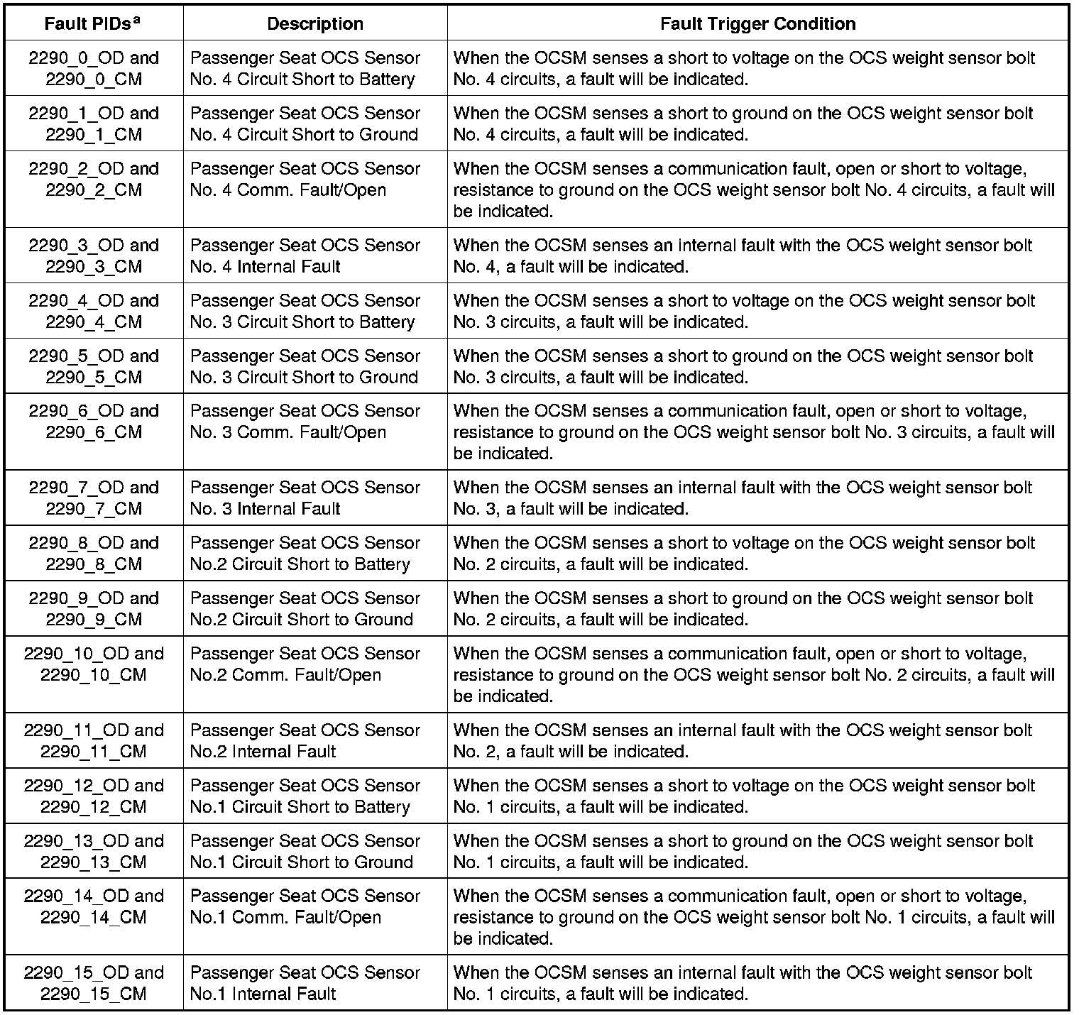
a Fault PIDs that end in OD indicate an on-demand status and are associated with on-demand DTC B2290. Fault PIDs that end in CM indicate continuous memory status and are associated with continuous DTC B2290.
This pinpoint test is intended to diagnose the following:
- Wiring, terminals or connectors
- OCS system component
PINPOINT TEST F: DTC B2290
WARNING: Do not handle, move or change the original horizontal mounting position of the restraints control module (RCM) while the RCM is connected and the ignition switch is ON. Failure to follow this instruction may result in the accidental deployment of the Safety Canopy(R) and cause serious personal injury or death.
WARNING: Never probe the electrical connectors on air bag, Safety Canopy(R) or side air curtain modules. Failure to follow this instruction may result in the accidental deployment of these modules, which increases the risk of serious personal injury or death.
WARNING: Never probe the electrical connectors on safety belt buckle/retractor pretensioners or adaptive load limiting retractors. Failure to follow this instruction may result in the accidental deployment of the safety belt pretensioners or adaptive load limiting retractors, which increases the risk of serious personal injury or death.
NOTICE: Use the correct probe adapter(s) from the Flex Probe Kit when making measurements. Failure to use the correct probe adapter(s) may damage the connector.
Most faults are due to connector and/or wiring concerns. Carry out a thorough inspection and verification before proceeding with the pinpoint test. Inspection and Verification
NOTE: Supplemental Restraint System (SRS) components should only be disconnected or reconnected when instructed to do so within a pinpoint test step. Failure to follow this instruction may result in incorrect diagnosis of the SRS.
NOTE: The SRS must be fully operational and free of faults before releasing the vehicle to the customer.
-------------------------------------------------
F1 RETRIEVE OCSM DTCs
- Enter the following diagnostic mode on the scan tool: Self Test - OCSM.
- Enter the following diagnostic mode on the scan tool: DataLogger - OCSM - View and Record All 2290 Fault PIDs.
- Refer to PID list in Normal Operation to view 2290 fault PIDs.
- Do any on-demand 2290 fault PIDs indicate a fault?
Yes
This fault cannot be cleared until it is corrected and the DTC is no longer retrieved on-demand during self-test. GO to F2.
No
This is an intermittent fault when present as a CMDTC only. GO to F36.
-------------------------------------------------
F2 CHECK THE SEAT WIRING AND CONNECTORS
- Ignition OFF.
- Depower the SRS. Refer to Supplemental Restraint System (SRS) Depowering and Repowering Supplemental Restraint System (SRS) Depowering and Repowering.
- Carry out a thorough visual inspection of the OCS system wiring, terminals and connectors and the related seat wiring harness and body wiring harness terminals and connectors.
- Were any problems noted?
Yes
REPAIR the seat connectors and wiring as needed.
Refer to Wiring Diagram Set 5, Connector Repair Procedures for schematic and connector information. Diagrams By Number
GO to F37.
No
Using the fault PIDs recorded in step F1, GO to the appropriate pinpoint test step.
For 2290_3_OD (Passenger Seat OCS Sensor No. 4 Internal Fault), 2290_7_OD (Passenger Seat OCS Sensor No. 3 Internal Fault), 2290_11_OD (Passenger Seat OCS
Sensor No.2 Internal Fault) or 2290_15_OD (Passenger Seat OCS Sensor No.1 Internal Fault), INSTALL a new OCS weight sensor bolt. REFER to Occupant Classification Sensor - Manual Seat Track Occupant Classification Sensor - Manual Seat Track or
Occupant Classification Sensor - Power Seat Track Occupant Classification Sensor - Power Seat Track.
For 2290_14_OD (Passenger Seat OCS Sensor No.1 Comm. Fault / Open), GO to F3.
For 2290_13_OD (Passenger Seat OCS Sensor No.1 Circuit Short to Ground), GO to F7.
For 2290_12_OD (Passenger Seat OCS Sensor No.1 Circuit Short to Battery), GO to F9.
For 2290_10_OD (Passenger Seat OCS Sensor No.2 Comm. Fault / Open), GO to F11.
For 2290_9_OD (Passenger Seat OCS Sensor No.2 Circuit Short to Ground), GO to F15.
For 2290_8_OD (Passenger Seat OCS Sensor No.2 Circuit Short to Battery), GO to F17.
For 2290_6_OD (Passenger Seat OCS Sensor No. 3 Comm. Fault/Open), GO to F19.
For 2290_5_OD (Passenger Seat OCS Sensor No. 3 Circuit Short to Ground), GO to F23.
For 2290_4_OD (Passenger Seat OCS Sensor No. 3 Circuit Short to Battery), GO to F25.
For 2290_2_OD (Passenger Seat OCS Sensor No. 4 Comm. Fault/Open), GO to F27.
For 2290_1_OD (Passenger Seat OCS Sensor No. 4 Circuit Short to Ground), GO to F31.
For 2290_0_OD (Passenger Seat OCS Sensor No. 4 Circuit Short to Battery), GO to F33.
-------------------------------------------------
F3 CHECK OCS WEIGHT SENSOR BOLT "1" CIRCUITS FOR AN OPEN
- Disconnect: OCSM C3159.
- Disconnect: OCS Weight Sensor Bolt "1" C3324.
- Measure the resistance between OCSM C3159, harness side and OCS sensor 1 C3324, harness side using the following chart.
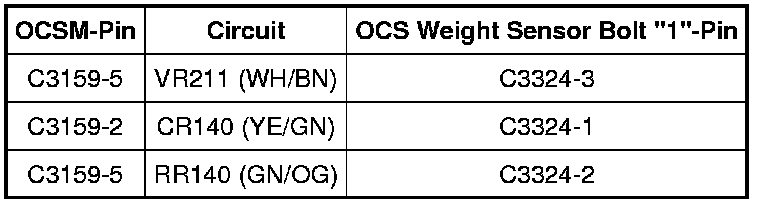
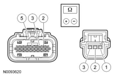
- Are the resistances less than 5 ohms?
Yes
GO to F4.
No
REPAIR circuit CR140 (YE/GN), circuit VR211 (WH/BN) or circuit RR140 (GN/OG).
Refer to Wiring Diagram Set 5, Connector Repair Procedures for schematic and connector information. Diagrams By Number
GO to F37.
-------------------------------------------------
F4 CHECK OCS WEIGHT SENSOR BOLT "1" FOR A SHORT BETWEEN CIRCUITS
- Measure the resistance between OCS weight sensor bolt "1":
- C3324-1, circuit CR140 (YE/GN), harness side and C3324-3, circuit VR211 (WH/BN), harness side.
- C3324-1, circuit CR140 (YE/GN), harness side and C3324-2, circuit RR140 (GN/OG), harness side.
- C3324-3, circuit VR211 (WH/BN), harness side and C3324-2, circuit RR140 (GN/OG), harness side.
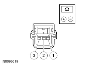
- Are the resistances greater than 10,000 ohms?
Yes
GO to F5.
No
REPAIR circuits CR140 (YE/GN), VR211 (WH/BN) and/or RR140 (GN/OG). GO to F37.
-------------------------------------------------
F5 CHECK OCS WEIGHT SENSOR BOLT "1" SIGNAL CIRCUIT FOR A SHORT TO VOLTAGE
- Disconnect: Passenger Seat Side Air Bag Module C327.
- Repower the SRS. Do not prove out the SRS at this time. Refer to Supplemental Restraint System (SRS) Depowering and Repowering Supplemental Restraint System (SRS) Depowering and Repowering.
- Ignition ON.
- Measure the voltage between OCS weight sensor bolt "1" C3324-3, circuit VR211 (WH/BN), harness side and ground.
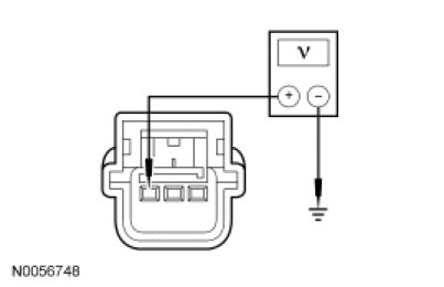
- Is any voltage present?
Yes
REPAIR circuit VR211 (WH/BN). GO to F37.
No
GO to F6.
-------------------------------------------------
F6 CHECK OCS WEIGHT SENSOR BOLT "1" SIGNAL CIRCUIT FOR A SHORT TO GROUND
- Ignition OFF.
- Measure the resistance between OCS weight sensor bolt "1" C3324-3, circuit VR211 (WH/BN), harness side and ground.

- Is the resistance greater than 10,000 ohms?
Yes
INSTALL a new OCS weight sensor bolt "1". REFER to Occupant Classification Sensor - Manual Seat Track Occupant Classification Sensor - Manual Seat Track or
Occupant Classification Sensor - Power Seat Track Occupant Classification Sensor - Power Seat Track. GO to F37.
No
REPAIR circuit VR211 (WH/BN). GO to F37.
-------------------------------------------------
F7 CHECK CIRCUIT VR211 (WH/BN) FOR A SHORT TO GROUND AND A SHORT TO CIRCUIT RR140 (GN/OG)
- Disconnect: OCS Weight Sensor Bolt "1" C3324.
- Disconnect: OCSM C3159.
- Measure the resistance between:
- OCS weight sensor bolt "1" C3324-3, circuit VR211 (WH/BN), harness side and C3324-2, circuit RR140 (GN/OG), harness side.
- OCS weight sensor bolt "1" C3324-3, circuit VR211 (WH/BN), harness side and ground.
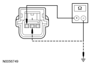
- Are the resistances greater than 10,000 ohms?
Yes
GO to F8.
No
REPAIR circuit VR211 (WH/BN) and/or circuit RR140 (GN/OG). GO to F37.
-------------------------------------------------
F8 CHECK OCS WEIGHT SENSOR BOLT "1" VREF CIRCUIT FOR AN OPEN
- Measure the resistance between OCS weight sensor bolt "1" C3324-1, circuit CR140 (YE/GN), harness side and OCSM C3159-2, circuit CR140 (YE/GN), harness side.
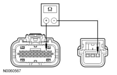
- Is the resistances less than 5 ohms?
Yes
GO to F35.
No
REPAIR circuit CR140 (YE/GN). GO to F37.
-------------------------------------------------
F9 CHECK OCS WEIGHT SENSOR BOLT "1" RETURN CIRCUIT FOR AN OPEN
- Disconnect: OCS Weight Sensor Bolt "1" C3324.
- Measure the resistance between OCS weight sensor bolt "1" C3324-2, circuit RR140 (GN/OG), harness side and ground.
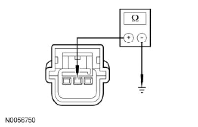
- Is the resistance less than 5 ohms?
Yes
GO to F10.
No
REPAIR circuit RR140 (GN/OG). GO to F37.
-------------------------------------------------
F10 CHECK OCS WEIGHT SENSOR BOLT "1" SIGNAL CIRCUIT FOR A SHORT TO VOLTAGE
- Disconnect: Passenger Seat Side Air Bag Module C327.
- Disconnect: OCSM C3159.
- Repower the SRS. Do not prove out the SRS at this time. Refer to Supplemental Restraint System (SRS) Depowering and Repowering Supplemental Restraint System (SRS) Depowering and Repowering.
- Ignition ON.
- Measure the voltage between OCS weight sensor bolt "1" C3324-3, circuit VR211 (WH/BN), harness side and ground.
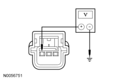
- Is any voltage present?
Yes
REPAIR circuit VR211 (WH/BN). GO to F37.
No
GO to F35.
-------------------------------------------------
F11 CHECK OCS WEIGHT SENSOR BOLT "2" CIRCUITS FOR AN OPEN
- Disconnect: OCSM C3159.
- Disconnect: OCS Weight Sensor Bolt "2" C3325.
- Measure the resistance between OCSM C3159, harness side and OCS sensor 2 C3325, harness side using the following chart.


- Are the resistances less than 0.5 ohm?
Yes
GO to F12.
No
REPAIR circuit CR141 (BN/YE), circuit VR212 (YE/GN) or circuit RR141 (VT/BN). GO to F37.
-------------------------------------------------
F12 CHECK FOR A SHORT BETWEEN OCS WEIGHT SENSOR BOLT "2" CIRCUITS
- Measure the resistance between OCS weight sensor bolt "2":
- C3325-1, circuit CR141 (BN/YE), harness side and C3325-3, circuit VR212 (YE/GN), harness side.
- C3325-1, circuit CR141 (BN/YE), harness side and C3325-2, circuit RR141 (VT/BN), harness side.
- C3325-3, circuit VR212 (YE/GN), harness side and C3325-2, circuit RR141 (VT/BN), harness side.
- Are the resistances greater than 10,000 ohms?
Yes
GO to F13.
No
REPAIR circuits CR141 (BN/YE), VR212 (YE/GN) and/or RR141 (VT/BN). GO to F37.
-------------------------------------------------
F13 CHECK OCS WEIGHT SENSOR BOLT "2" SIGNAL CIRCUIT FOR A SHORT TO VOLTAGE
- Disconnect: Passenger Seat Side Air Bag Module C327.
- Repower the SRS. Do not prove out the SRS at this time. Refer to Supplemental Restraint System (SRS) Depowering and Repowering Supplemental Restraint System (SRS) Depowering and Repowering.
- Ignition ON.
- Measure the voltage between OCS weight sensor bolt "2" C3325-3, circuit VR212 (YE/GN), harness side and ground.
- Is any voltage present?
Yes
REPAIR circuit VR212 (YE/GN). GO to F37.
No
GO to F14.
-------------------------------------------------
F14 CHECK OCS WEIGHT SENSOR BOLT "2" SIGNAL CIRCUIT FOR A SHORT TO GROUND
- Ignition OFF.
- Measure the resistance between OCS weight sensor bolt "2" C3325-3, circuit VR212 (YE/GN), harness side and ground.
- Is the resistance greater than 10,000 ohms?
Yes
INSTALL a new OCS weight sensor bolt "2". REFER to Occupant Classification Sensor - Manual Seat Track Occupant Classification Sensor - Manual Seat Track or
Occupant Classification Sensor - Power Seat Track Occupant Classification Sensor - Power Seat Track. GO to F37.
No
REPAIR circuit VR212 (YE/GN). GO to F37.
-------------------------------------------------
F15 CHECK CIRCUIT VR212 (YE/GN) FOR A SHORT TO GROUND AND A SHORT TO CIRCUIT RR141 (VT/BN)
- Disconnect: OCS Weight Sensor Bolt "2" C3325.
- Disconnect: OCSM C3159.
- Measure the resistance between:
- OCS weight sensor bolt "2" C3325-3, circuit VR212 (YE/GN), harness side and ground.
- OCS weight sensor bolt "2" C3325-3, circuit VR212 (YE/GN), harness side and C3325-2, circuit RR141 (VT/BN), harness side.
- Are the resistances greater than 10,000 ohms?
Yes
GO to F16.
No
REPAIR circuits VR212 (YE/GN) and RR141 (VT/BN). GO to F37.
-------------------------------------------------
F16 CHECK OCS WEIGHT SENSOR BOLT "2" VREF CIRCUIT FOR AN OPEN
- Measure the resistance between OCS weight sensor bolt "2" C3325-1, circuit CR141 (BN/YE), and OCSM C3159-10, circuit CR141 (BN/YE), harness side.
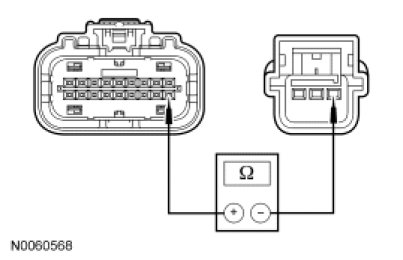
- Is the resistances less than 5 ohms?
Yes
GO to F35.
No
REPAIR circuit CR141 (BN/YE). GO to F37.
-------------------------------------------------
F17 CHECK OCS WEIGHT SENSOR BOLT "2" RETURN CIRCUIT FOR AN OPEN
- Disconnect: OCS Weight Sensor Bolt "2" C3325.
- Measure the resistance between OCS weight sensor bolt "2" C3325-2, circuit RR141 (VT/BN), harness side and ground.
- Is the resistance less than 5 ohms?
Yes
GO to F18.
No
REPAIR circuit RR141 (VT/BN). GO to F37.
-------------------------------------------------
F18 CHECK OCS WEIGHT SENSOR BOLT "2" SIGNAL CIRCUIT FOR A SHORT TO VOLTAGE
- Disconnect: Passenger Seat Side Air Bag Module C327.
- Disconnect: OCSM C3159.
- Repower the SRS. Do not prove out the SRS at this time. Refer to Supplemental Restraint System (SRS) Depowering and Repowering Supplemental Restraint System (SRS) Depowering and Repowering.
- Ignition ON.
- Measure the voltage between OCS weight sensor bolt "2" C3325-3, circuit VR212 (YE/GN), harness side and ground.
- Is any voltage present?
Yes
REPAIR circuit VR212 (YE/GN). GO to F37.
No
GO to F35.
-------------------------------------------------
F19 CHECK OCS WEIGHT SENSOR BOLT "3" CIRCUITS FOR AN OPEN
- Disconnect: OCSM C3159.
- Disconnect: OCS Weight Sensor Bolt "3" C3330.
- Measure the resistance between OCSM C3159, harness side and OCS sensor 3 C3330, harness side using the following chart.
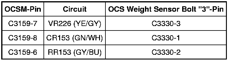

- Are the resistances less than 5 ohms?
Yes
GO to F20.
No
REPAIR circuit CR153 (GN/WH), VR226 (YE/GY) or RR153 (GY/BU). GO to F37.
-------------------------------------------------
F20 CHECK FOR A SHORT BETWEEN OCS WEIGHT SENSOR BOLT "3" CIRCUITS
- Measure the resistance between OCS weight sensor bolt "3":
- C3330-1, circuit CR153 (GN/WH), harness side and C3330-3, circuit VR226 (YE/GY), harness side.
- C3330-1, circuit CR153 (GN/WH), harness side and C3330-2, circuit RR153 (GY/BU), harness side.
- C3330-3, circuit VR226 (YE/GY), harness side and C3330-2, circuit RR153 (GY/BU), harness side.
- Are the resistances greater than 10,000 ohms?
Yes
GO to F21.
No
REPAIR the affected circuits CR153 (GN/WH), VR226 (YE/GY) and/or RR153 (GY/BU). GO to F37.
-------------------------------------------------