Timing Cover: Service and Repair
Engine Front Cover
Skid Plate

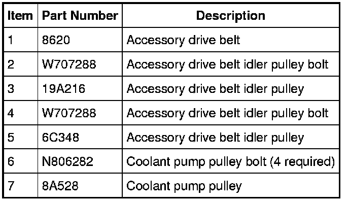
Accessory Drive Components
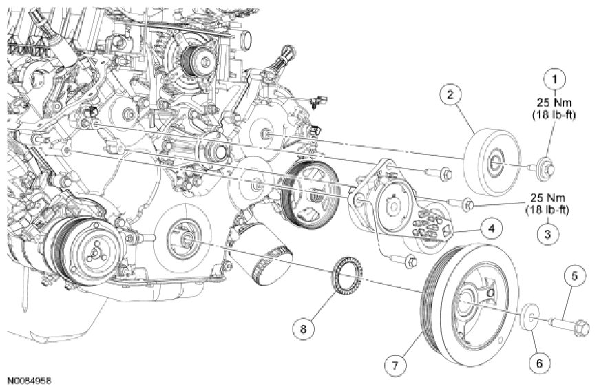
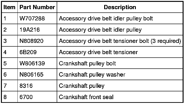
Accessory Drive Components (Continued)
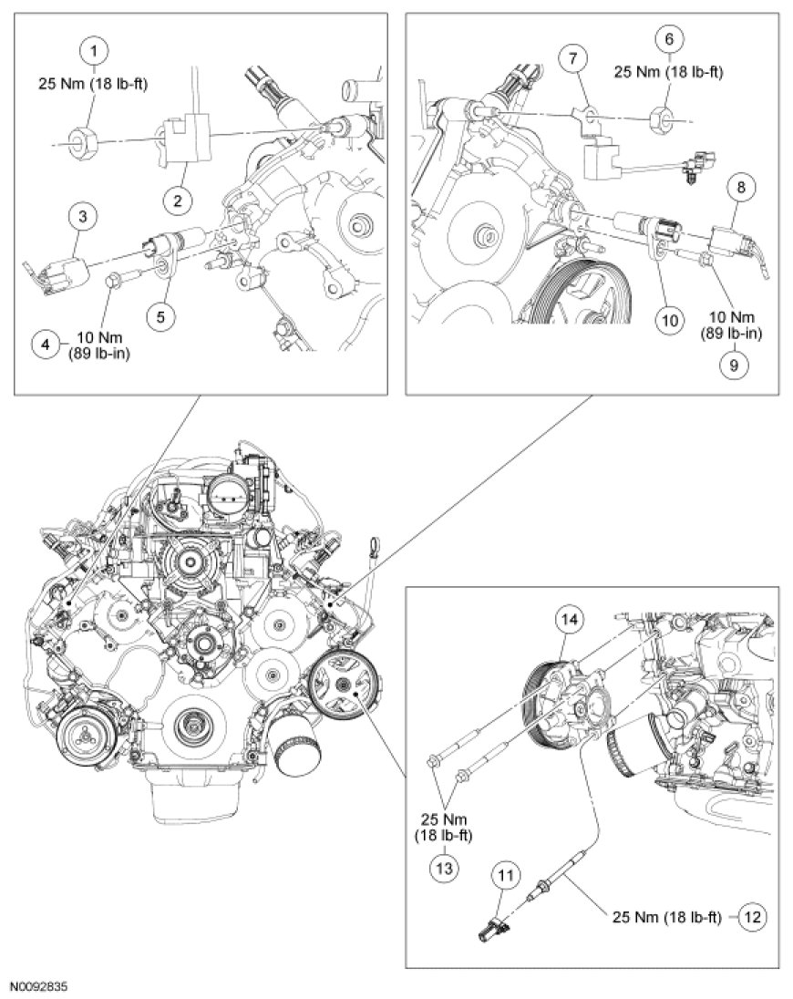
Electrical and Power Steering Components
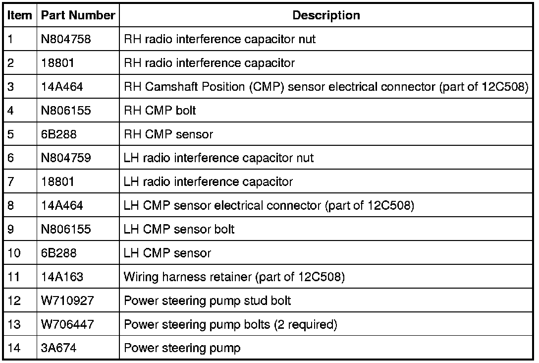
Engine Front Cover
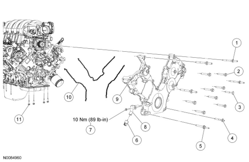
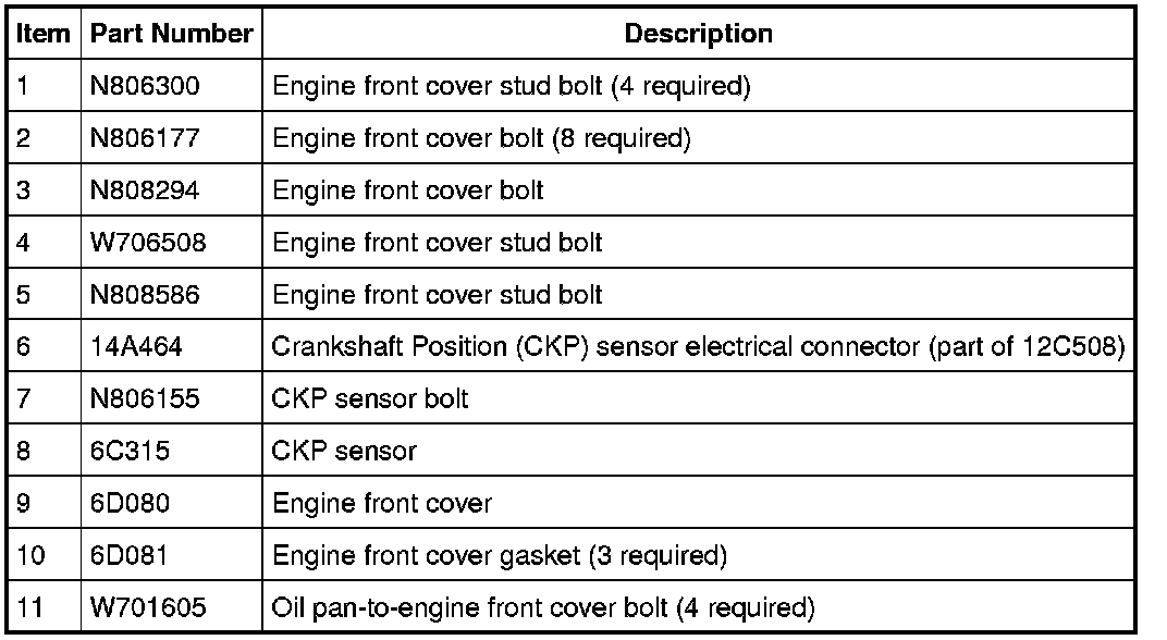
Removal
1. With the vehicle in NEUTRAL, position it on a hoist.
2. Remove the RH valve cover. For additional information, refer to Valve Cover - RH Valve Cover - RH.
3. Remove the LH valve cover. For additional information, refer to Valve Cover - LH Valve Cover - LH.
4. Remove the engine cooling fan.
5. Loosen the 4 coolant pump pulley bolts.
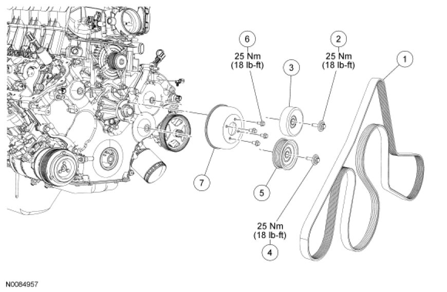
6. Rotate the tensioner clockwise and remove the accessory drive belt.

7. Remove the 4 bolts and the coolant pump pulley.
8. Remove the drain plug and drain the engine oil. Install the drain plug when finished.
- Tighten to 23 Nm (17 lb-ft).

9. Remove the pushpin, press the position retaining tab and rotate the lower cooling fan shroud upward until the position retainer tab locks into position.

10. Remove the starter wiring harness bracket bolt at the starter.

11. Remove the nut and position the transmission cooler tube support bracket and the starter wiring harness support bracket aside.

12. Disconnect the Crankshaft Position (CKP) sensor electrical connector.
13. Remove the nut and position aside the Power Steering Pressure (PSP) hose support bracket.

14. Remove the crankshaft pulley bolt and washer.
- Discard the crankshaft pulley bolt.
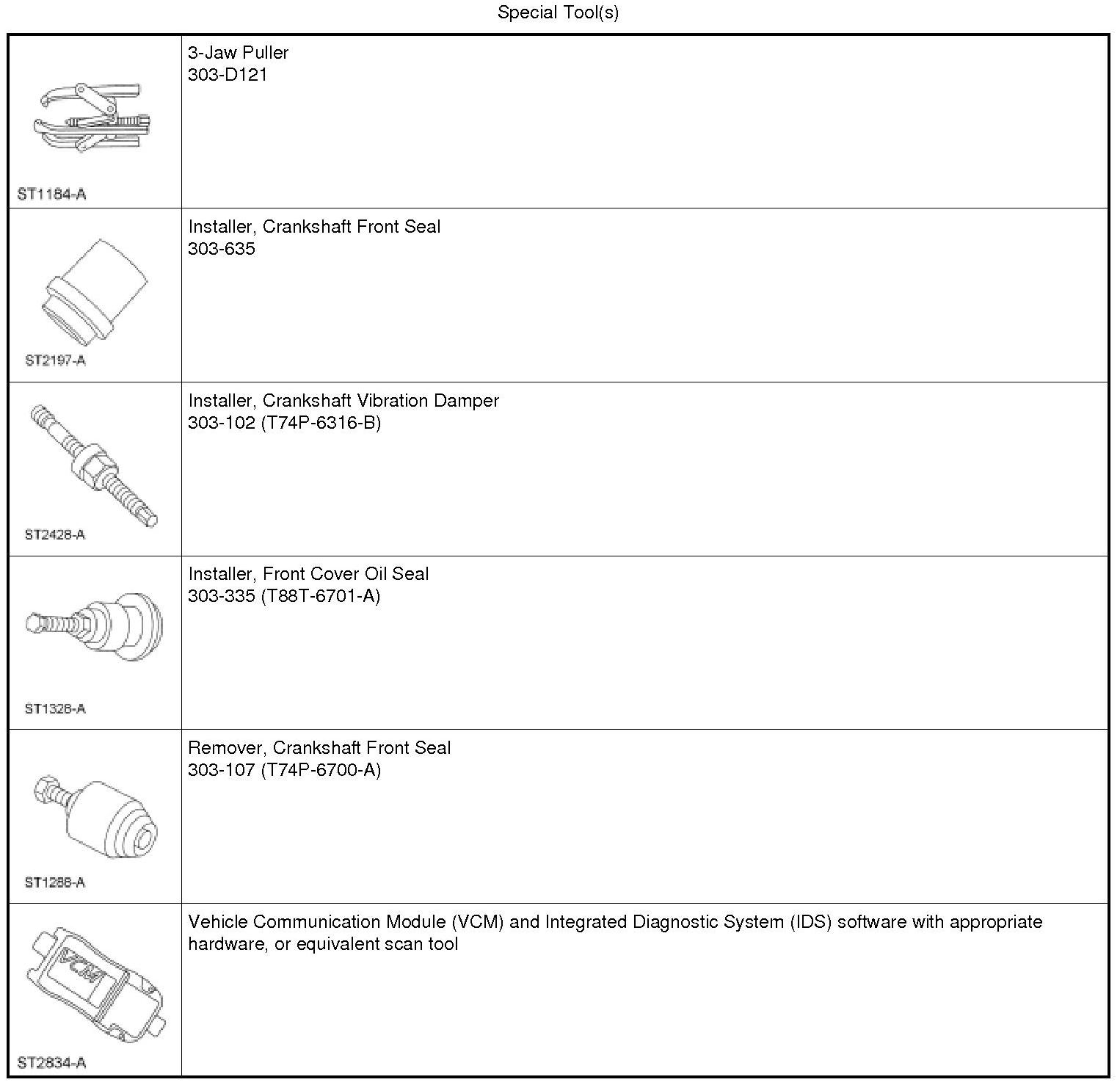
15. Using the 3-Jaw Puller, remove the crankshaft pulley.

16. Using the Crankshaft Front Seal Remover, remove and discard the crankshaft front seal.

17. Remove the 3 bolts and the 3 accessory drive idler pulleys.
18. Remove the 3 bolts and the accessory drive belt tensioner.
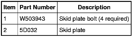
19. If equipped, remove the 4 bolts and the skid plate.
20. Remove the 4 front oil pan bolts.
21. Disconnect the wiring harness retainer, remove the 2 bolts, the stud bolt and position aside the power steering pump.
22. Disconnect the RH Camshaft Position (CMP) sensor electrical connector.
23. Remove the bolt and the RH CMP sensor.
24. Remove the nut and position the RH radio ignition interference capacitor aside.
25. Disconnect the LH CMP sensor electrical connector.
26. Remove the bolt and the LH CMP sensor.
27. Remove the nut and position the LH radio ignition interference capacitor aside.
28. Remove the 9 bolts and the 6 stud bolts.
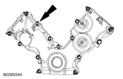
29. Remove the engine front cover from the front cover-to-cylinder block dowel.
- Remove and discard the 3 engine front cover gaskets.

30. Remove the bolt and the CKP sensor.
- Discard the O-ring seal.
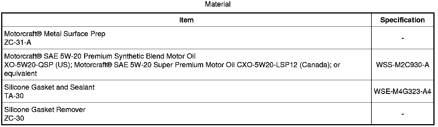
31. NOTICE: Do not use metal scrapers, wire brushes, power abrasive discs or other abrasive means to clean the sealing surfaces. These tools cause scratches and gouges which make leak paths. Use a plastic scraping tool to remove all traces of old sealant.
Clean the mating surfaces with silicone gasket remover and metal surface prep. Follow the directions on the packaging.
- Inspect the mating surfaces.
Installation
1. Install a new O-ring seal on the CKP sensor. Lubricate the new O-ring seal with clean engine oil.
2. Install the CKP sensor and the bolt.
- Tighten to 10 Nm (89 lb-in).
3. NOTICE: Do not use metal scrapers, wire brushes, power abrasive discs or other abrasive means to clean the sealing surfaces. These tools cause scratches and gouges which make leak paths. Use a plastic scraping tool to remove all traces of old sealant.
NOTE: If the engine front cover is not secured within 4 minutes, the sealant must be removed and the sealing area cleaned. To clean the sealing area, use silicone gasket remover and metal surface prep. Allow to dry until there is no sign of wetness, or 4 minutes, whichever is longer. Follow the directions on the packaging. Failure to follow this procedure can cause future oil leakage.
NOTE: Make sure that the engine front cover gaskets are in place on the engine front cover before installation.
Apply a bead of silicone gasket and sealant along the cylinder head-to-cylinder block surface and the oil pan-to-cylinder block surface, at the locations shown.

4. Install 3 new engine front cover gaskets on the engine front cover. Position the engine front cover onto the dowels. Install the 15 fasteners finger-tight.

5. Tighten the 15 engine front cover fasteners in the sequence shown in 2 stages.
- Stage 1: Tighten fasteners 1 through 15 to 25 Nm (18 lb-ft).
- Stage 2: Tighten fasteners 6 and 7 to 48 Nm (35 lb-ft).


6. Loosely install the 4 bolts, then tighten the bolts in 2 stages, in the sequence shown.
- Stage 1: Tighten to 20 Nm (177 lb-in).
- Stage 2: Tighten an additional 60 degrees.

7. Connect the CKP sensor electrical connector.
8. Position the starter wiring harness support bracket and the transmission cooler tube support bracket and tighten the nut.
- Tighten to 10 Nm (89 lb-in).
9. Install the starter wiring harness bracket bolt at the starter.
- Tighten to 10 Nm (89 lb-in).
10. Lubricate the engine front cover and the new crankshaft seal inner lip with clean engine oil.

11. Using the Front Cover Oil Seal Installer, the Crankshaft Front Seal Installer and the Crankshaft Vibration Damper Installer, install a new crankshaft front seal into the engine front cover.

12. NOTE: If not secured within 4 minutes, the sealant must be removed and the sealing area cleaned with metal surface prep and silicone gasket remover. Follow the directions on the packaging. Allow to dry until there is no sign of wetness, or 4 minutes, whichever is longer. Failure to follow this procedure can cause future oil leakage.
Apply silicone gasket and sealant to the Woodruff key slot on the crankshaft pulley.

13. Use the Crankshaft Vibration Damper Installer to install the crankshaft pulley.

14. Position the washer on the new crankshaft pulley bolt and install the new crankshaft pulley bolt finger-tight. Tighten the new crankshaft pulley bolt in 4 stages.
- Stage 1: Tighten to 120 Nm (89 lb-ft).
- Stage 2: Loosen 360 degrees.
- Stage 3: Tighten to 50 Nm (37 lb-ft).
- Stage 4: Tighten an additional 90 degrees.

15. Press the retaining tab and rotate the lower cooling fan shroud downward until the position tab retainer locks into place and install the pushpin.
16. Install the accessory drive belt tensioner and the 3 bolts.
- Tighten to 25 Nm (18 lb-ft).
17. Install the 3 accessory drive idler pulleys and the 3 bolts.
- Tighten to 25 Nm (18 lb-ft).
18. Position the coolant pump pulley and install the 4 bolts finger-tight.
19. If equipped, install the skid plate and the 4 bolts.
- Tighten to 25 Nm (18 lb-ft).
20. Position the power steering pump and install the 2 bolts and the stud bolt.
- Tighten to 25 Nm (18 lb-ft).
21. Attach the engine wiring harness to the power steering pump stud bolt.
22. Position the PSP hose support bracket and install the nut.
- Tighten to 40 Nm (30 lb-ft).
23. NOTE: Lubricate the O-ring seal with clean engine oil prior to installation.
Install the RH CMP sensor and the bolt.
- Tighten to 10 Nm (89 lb-in).
24. Connect the RH CMP sensor electrical connector.
25. Install the RH radio ignition interference capacitor and the nut.
- Tighten to 25 Nm (18 lb-ft).
26. NOTE: Lubricate the O-ring seal with clean engine oil prior to installation.
Install the LH CMP sensor and the bolt.
- Tighten to 10 Nm (89 lb-in).
27. Connect the LH CMP sensor electrical connector.
28. Install the LH radio ignition interference capacitor and the nut.
- Tighten to 10 Nm (89 lb-in).
29. Rotate the tensioner clockwise and install the accessory drive belt.
30. Tighten the 4 coolant pump pulley bolts.
- Tighten to 25 Nm (18 lb-ft).
31. Install the engine cooling fan.
32. Install the LH valve cover. For additional information, refer to Valve Cover - LH Valve Cover - LH.
33. Install the RH valve cover. For additional information, refer to Valve Cover - RH Valve Cover - RH.
34. Fill the crankcase with clean engine oil.
35. Using the scan tool, perform the Misfire Monitor Neutral Profile Correction procedure, following the on-screen instructions.