Pinpoint Test L: Poor Vehicle Tracking During Anti-Lock Function
Anti-Lock Control
Pinpoint Test L: Poor Vehicle Tracking During Anti-Lock Function
Refer to Wiring Diagram Set 42, Vehicle Dynamic Systems for schematic and connector information. Diagrams By Number
Normal Operation
The ABS module uses input from several different sensors (wheel speed sensors, Brake Pedal Position (BPP) switch, sensor cluster, etc.) to determine if an ABS event is necessary. If an ABS event is necessary, the ABS module will command the hydraulic pump motor on and command the Hydraulic Control Unit (HCU) to actuate the appropriate solenoids. During an ABS event, the front and rear end of the vehicle should track true to the direction of travel along the vehicle centerline unless driver input dictates otherwise, there is an internal issue with the HCU or an issue with the base brake system (caliper, tubes, etc.) that allows one or more wheels to lock up.
The operating voltage required for ABS module, hydraulic pump and isolation valve operation is in a range between 10 and 17 volts. Fused battery voltage is supplied to the ABS module by Battery Junction Box (BJB) fuse 36 (30A) along circuit SBB36 (GN/RD) and by BJB fuse 47 (60A) along circuit SBB47 (WH/RD). Fused ignition voltage is supplied to the ABS module by BJB fuse 54 (5A) along circuit CBB54 (VT/OG). Ground is provided along circuit GD121 (BK/YE).
This pinpoint test is intended to diagnose the following:
- Base brake system
- HCU
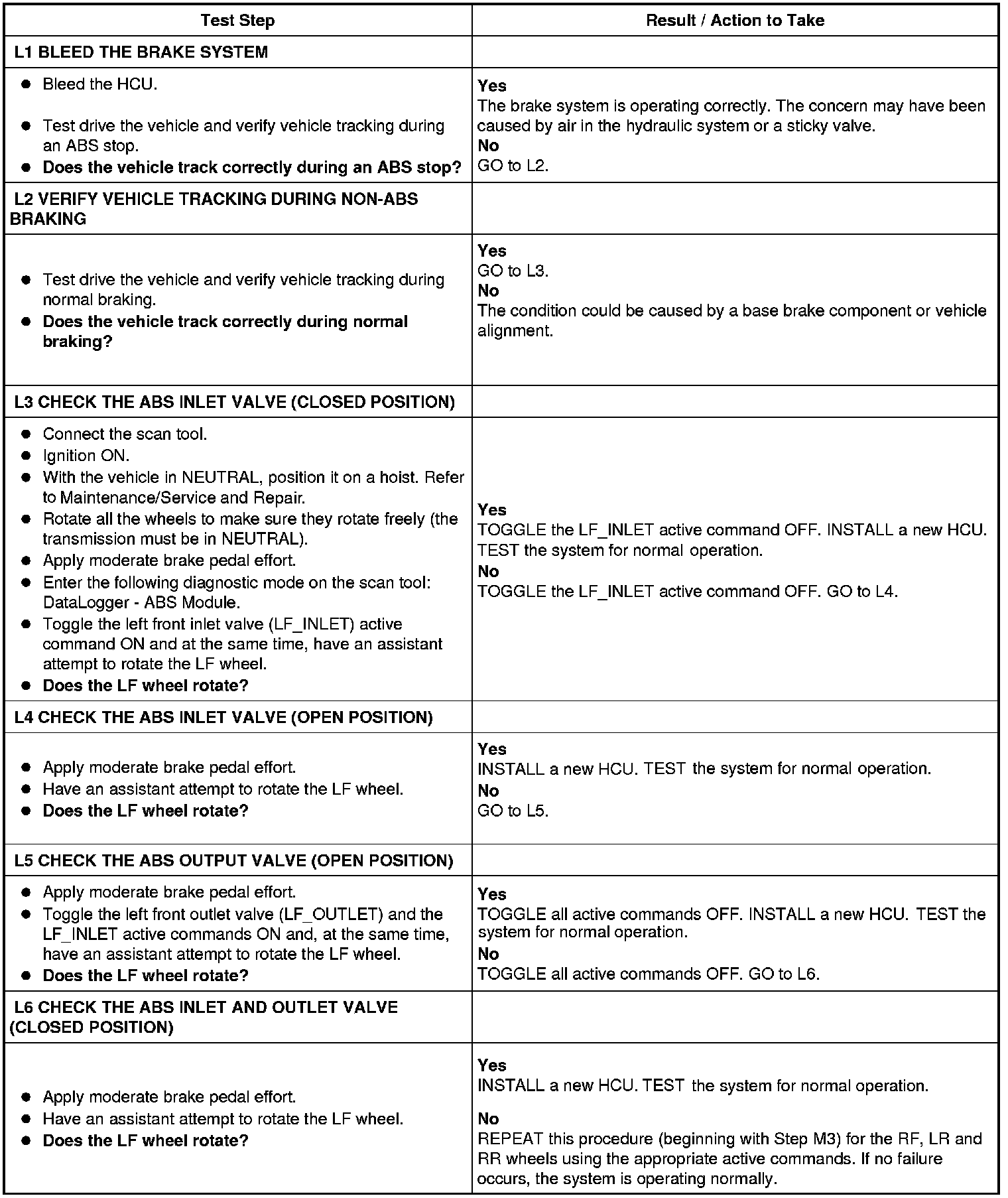
PINPOINT TEST L: POOR VEHICLE TRACKING DURING ANTI-LOCK FUNCTION
L1-L6: