Pinpoint Test A: The Speed Control Is Inoperative
Speed Control
Pinpoint Tests
Pinpoint Test A: The Speed Control Is Inoperative
Refer to Wiring Diagram Set 31, Speed Control for schematic and connector information. Diagrams By Number
Normal Operation
The PCM sends a signal through circuit VES10 (WH) to the speed control switches, which passes through the clockspring. The return signal is sent through circuit RES08 (GN/BN) and the clockspring. A varying voltage is created as different speed control command switches are pressed. The stoplamp switch sends a voltage signal through circuit CCB08 (VT/WH) to the PCM when the brake pedal is applied, and deactivates the speed control if engaged.
Vehicles equipped with a gasoline engine and manual transmission have an additional Clutch Pedal Position (CPP) switch. The PCM sends a signal to the CPP switch through circuit CE904 (GN/VT). The CPP switch, normally closed with the clutch pedal released, then routes the signal to ground through circuit GD113 (BK/YE). When the clutch pedal is applied, the CPP switch moves to the open position causing the PCM to lose the ground signal and deactivate the speed control.
Vehicles equipped with a diesel engine and manual transmission have an additional CPP switch. The CPP switch, normally closed, supplies a voltage signal to the PCM through circuit CE904 (GN/VT). When the clutch pedal is applied, the CPP switch moves to the open position causing the PCM to lose the voltage signal and deactivate the speed control.
The speed control deactivator switch interrupts the power signal to the PCM through circuit CES09 (VT/OG) when the brake pedal is applied firmly and passes the stoplamp switch trip point. This is a redundant signal to the PCM.
This pinpoint test is intended to diagnose the following:
- Wiring, terminals or connectors
- PCM not configured for speed control
- Speed control switches
- Stoplamp switch
- Speed control deactivator switch
- CPP switch (manual transmission)
- Digital Transmission Range (TR) sensor (automatic transmission)
- PCM
PINPOINT TEST A: THE SPEED CONTROL IS INOPERATIVE
-------------------------------------------------
A1 VERIFY PCM CONFIGURATION
- Enter the following diagnostic mode on the scan tool: Programmable Parameters.
- Verify that the speed control is enabled in the PCM.
- Is the speed control enabled?
Yes
GO to A2.
No
ENABLE the speed control in the PCM using the scan tool programmable parameters menu. TEST the system for normal operation.
-------------------------------------------------
A2 CHECK FOR DTCs
- Review the recorded DTCs from the PCM self-test.
- Are any DTCs recorded?
Yes
REFER to DTC Charts. Diagnostic Trouble Code Tests and Associated Procedures
No
GO to A3.
-------------------------------------------------
A3 CHECK THE VEHICLE SPEED
- Check for correct operation of the speedometer.
- Does the speedometer operate correctly?
Yes
GO to A4.
No
REFER to Instrument Panel, Gauges and Warning Indicators to diagnose the speedometer.
-------------------------------------------------
A4 CHECK THE STOPLAMP SWITCH (BOO) AND SPEED CONTROL DEACTIVATOR SWITCH (BPA) PIDs
- Enter the following diagnostic mode on the scan tool: PCM DataLogger.
- Monitor the PCM PIDs BOO (brake pedal top travel) and BPA (speed control deactivator switch) while applying and releasing the brake pedal as follows:
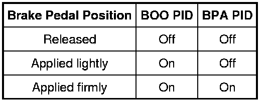
- Do the PID values agree with the brake pedal position?
Yes
If equipped with an automatic transmission, GO to A6.
If equipped with a manual transmission, GO to A5.
No
Go To Pinpoint Test B. Pinpoint Test B: DTC P1703 Or DTC P1572
-------------------------------------------------
A5 CHECK THE CPP SWITCH (CPP_TOP) PID
- Enter the following diagnostic mode on the scan tool: PCM DataLogger.
- Monitor the PCM PID CPP_TOP while pressing and releasing the clutch pedal.
- Does the PID value agree with the clutch pedal position?
Yes
GO to A7.
No
For vehicles equipped with gasoline engine, Go To Pinpoint Test D. Pinpoint Test D: The Speed Control Does Not Disengage When The Clutch Is Applied
For vehicles equipped with diesel engine, Go To Pinpoint Test E.
-------------------------------------------------
A6 MONITOR THE TR PID
- Enter the following diagnostic mode on the scan tool: PCM DataLogger.
- Monitor the PCM PID (TR).
- Select DRIVE.
- Does the PID value agree with the TR selector lever position?
Yes
GO to A7.
No
REFER to Transmission Control Systems to continue diagnosis of the digital TR sensor. Testing and Inspection
-------------------------------------------------
A7 CHECK THE SPEED CONTROL SWITCH
- Enter the following diagnostic mode on the scan tool: PCM DataLogger.
- Press each speed control switch button while monitoring the speed control switch PID (SCCS).
SCCS PID Values
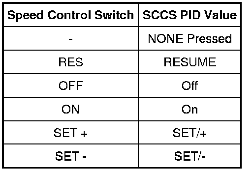
- Does the PID value agree with the switch position?
Yes
GO to A8.
No
If only one switch does not display the correct PID value, INSTALL a new speed control switch. REFER to Speed Control Switch Speed Control Switch. TEST the system for normal operation.
Otherwise, Go To Pinpoint Test C. Pinpoint Test C: Speed Control Switch Stuck Or Circuit Failure
-------------------------------------------------
A8 CHECK FOR CORRECT PCM OPERATION
- Disconnect all the PCM connectors.
- Check for:
- corrosion
- damaged pins
- pushed-out pins
- Connect all the PCM connectors and make sure they are seated correctly.
- Operate the system and verify the concern is still present.
- Is the concern still present?
Yes
INSTALL a new PCM. TEST the system for normal operation.
No
The system is operating correctly at this time. The concern may have been caused by a loose or corroded connector.
-------------------------------------------------