Pinpoint Test C: Speed Control Switch Stuck Or Circuit Failure
Speed Control
Pinpoint Tests
Pinpoint Test C: Speed Control Switch Stuck or Circuit Failure
Refer to Wiring Diagram Set 31, Speed Control for schematic and connector information. Diagrams By Number
Normal Operation
The PCM sends a signal through circuit VES10 (WH) to the speed control switches which passes through the clockspring. A varying voltage is created as different speed control command switches are pressed. Circuit RES08 (GN/BN) provides a signal return.
P0565-P0581:
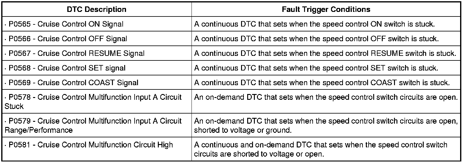
This pinpoint test is intended to diagnose the following:
- Wiring, terminals or connectors
- Clockspring
- PCM
PINPOINT TEST C: SPEED CONTROL SWITCH STUCK OR CIRCUIT FAILURE
NOTICE: Use the correct probe adapter(s) when making measurements. Failure to use the correct probe adapter(s) may damage the connector.
-------------------------------------------------
C1 CHECK THE SPEED CONTROL SWITCH
- Ignition ON.
- Enter the following diagnostic mode on the scan tool: PCM DataLogger.
- Press each speed control switch button while monitoring the speed control switch PID (SCCS).
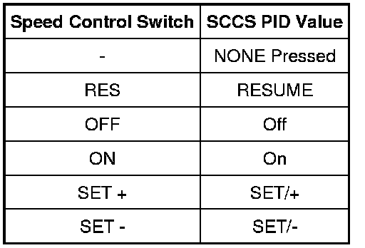
- Does the PID value agree with the switch position?
Yes
The system is operating correctly at this time. CLEAR the DTCs. TEST the system for normal operation.
No
If only one switch does not display the correct PID value, INSTALL a new speed control switch. REFER to Speed Control Switch Speed Control Switch. CLEAR the DTCs. TEST the system for normal operation.
Otherwise, GO to C2.
-------------------------------------------------
C2 CHECK THE SPEED CONTROL SWITCH CIRCUITRY FOR A SHORT TO VOLTAGE
- Ignition OFF.
- Disconnect: PCM C175b (Gasoline) or PCM C1232b (Diesel).
- Ignition ON.
- Turn the parking lamps on.
- For gasoline vehicles, measure the voltage between the PCM C175b-19, circuit VES10 (WH), harness side and ground; and between the PCM C175b-30, circuit RES08 (GN/BN), harness side and ground.
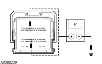
- For diesel vehicles, measure the voltage between the PCM C1232b-8, circuit VES10 (WH), harness side and ground; and between the PCM C1232b-17, circuit RES08 (GN/BN), harness side and ground.
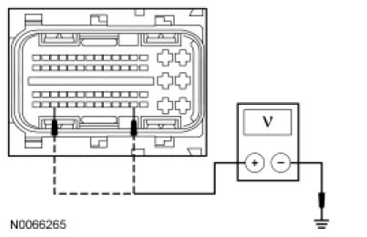
- Is any voltage present?
Yes
TURN the parking lamps off. GO to C3.
No
TURN the parking lamps off. GO to C5.
-------------------------------------------------
C3 CHECK CIRCUITS VES10 (WH) AND RES08 (GN/BN) FOR A SHORT TO VOLTAGE
- Ignition OFF.
- Disconnect: Clockspring C218a.
- Ignition ON.
- For gasoline vehicles, measure the voltage between the PCM C175b-19, circuit VES10 (WH), harness side and ground; and between the PCM C175b-30, circuit RES08 (GN/BN), harness side and ground.
- For diesel vehicles, measure the voltage between the PCM C1232b-8, circuit VES10 (WH), harness side and ground; and between the PCM C1232b-17, circuit RES08 (GN/BN), harness side and ground.
- Is any voltage present?
Yes
REPAIR the circuit in question. CLEAR the DTCs. REPEAT the self-test.
No
GO to C4.
-------------------------------------------------
C4 CHECK THE CLOCKSPRING FOR A SHORT TO VOLTAGE
- Ignition OFF.
- Connect: Clockspring C218a.
- Remove the driver air bag module.
- Disconnect: Upper Clockspring C218b.
- WARNING: Prior to reinstalling a previously removed driver air bag module, make sure to correctly position the wire clip that retains the driver air bag module to the steering wheel. Failure to follow this instruction will result in incorrect installation of the driver air bag module and increases the risk of serious personal injury or death in a crash.
- Connect the battery.
- Ignition ON.
- Turn the parking lamps on.
- For gasoline vehicles, measure the voltage between the PCM C175b-19, circuit VES10 (WH), harness side and ground; and between the PCM C175b-30, circuit RES08 (GN/BN), harness side and ground.
- For diesel vehicles, measure the voltage between the PCM C1232b-8, circuit VES10 (WH), harness side and ground; and between the PCM C1232b-17, circuit RES08 (GN/BN), harness side and ground.
- Is any voltage present?
Yes
INSTALL a new clockspring. INSTALL the driver air bag module. CLEAR the DTCs. REPEAT the self-test.
No
GO to C11.
-------------------------------------------------
C5 CHECK THE SPEED CONTROL SWITCH CIRCUITRY FOR A SHORT TO GROUND
- Ignition OFF.
- Remove the driver air bag module.
- Disconnect: Upper Clockspring C218b.
- For gasoline vehicles, measure the resistance between the PCM C175b-19, circuit VES10 (WH), harness side and ground; and between the PCM C175b-30, circuit RES08 (GN/BN), harness side and ground.
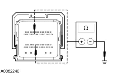
- For diesel vehicles, measure the resistance between the PCM C1232b-8, circuit VES10 (WH), harness side and ground; and between the PCM C1232b-17, circuit RES08 (GN/BN), harness side and ground.
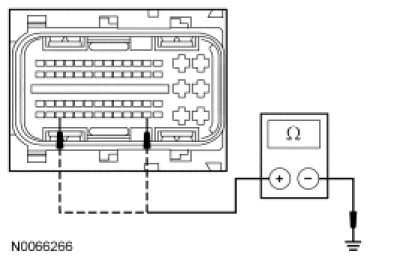
- Are the resistances greater than 10,000 ohms?
Yes
GO to C7.
No
GO to C6.
-------------------------------------------------
C6 CHECK THE CLOCKSPRING FOR A SHORT TO GROUND
- Disconnect: Clockspring C218a.
- For gasoline vehicles, measure the resistance between the PCM C175b-19, circuit VES10 (WH), harness side and ground; and between the PCM C175b-30, circuit RES08 (GN/BN), harness side and ground.
- For diesel vehicles, measure the resistance between the PCM C1232b-8, circuit VES10 (WH), harness side and ground; and between the PCM C1232b-17, circuit RES08 (GN/BN), harness side and ground.
- Are the resistances greater than 10,000 ohms?
Yes
INSTALL a new clockspring. INSTALL the driver air bag module. CLEAR the DTCs. TEST the system for normal operation.
No
REPAIR the circuit in question. INSTALL the driver air bag module. CLEAR the DTCs. TEST the system for normal operation.
-------------------------------------------------
C7 CHECK CIRCUITS VES10 (WH) AND RES08 (GN/BN) FOR AN OPEN
- Disconnect: Clockspring C218a.
- For gasoline vehicles, measure the resistance between the PCM C175b-19, circuit VES10 (WH), harness side and the clockspring C218a-15, circuit VES10 (WH), harness side.
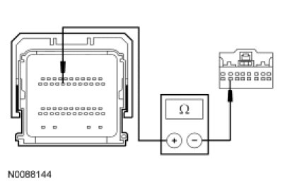
- For gasoline vehicles, measure the resistance between the PCM C175b-30, circuit RES08 (GN/BN), harness side and the clockspring C218a-14, circuit RES08 (GN/BN), harness side.
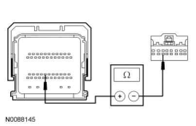
- For diesel vehicles, measure the resistance between the PCM C1232b-8, circuit VES10 (WH), harness side and the clockspring C218a-15, circuit VES10 (WH), harness side.
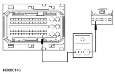
- For diesel vehicles, measure the resistance between the PCM C1232b-17, circuit RES08 (GN/BN), harness side and the clockspring C218a-14, circuit RES08 (GN/BN), harness side.
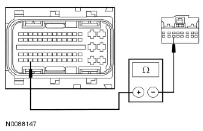
- Are the resistances less than 5 ohms?
Yes
GO to C8.
No
REPAIR the circuit in question. CLEAR the DTCs. TEST the system for normal operation.
-------------------------------------------------
C8 CHECK THE CLOCKSPRING FOR AN OPEN
- Measure the resistance between the clockspring C218 pin 14, component side and the upper clockspring pin 9, component side.
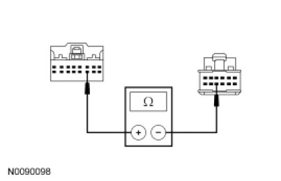
- Measure the resistance between the clockspring C218 pin 15, component side and the upper clockspring pin 8, component side.
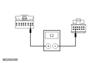
- Are the resistances less than 5 ohms?
Yes
GO to C9.
No
INSTALL a new clockspring. INSTALL the driver air bag module. CLEAR the DTCs. REPEAT the self-test.
-------------------------------------------------
C9 CHECK THE SPEED CONTROL SWITCH CIRCUITRY FOR A SHORT TOGETHER
- Connect: Clockspring C218a.
- Connect: Upper Clockspring C218b.
- For gasoline vehicles, measure the resistance between the PCM C175b-19, circuit VES10 (WH), harness side and the PCM C175b-30, circuit RES08 (GN/BN), harness side.
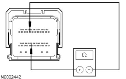
- For diesel vehicles, measure the resistance between the PCM C1232b-8, circuit VES10 (WH), harness side and the PCM C1232b-17, circuit RES08 (GN/BN), harness side.
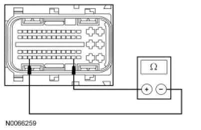
- Is the resistance between 4,100 and 4,550 ohms?
Yes
GO to C11.
No
GO to C10.
-------------------------------------------------
C10 CHECK THE STEERING WHEEL SWITCH HARNESS
- Check the steering wheel switch harness for an open, short to ground or short to voltage.
- Are any of these conditions present?
Yes
REPAIR the steering wheel switch harness. CLEAR the DTCs. REPEAT the self-test.
No
INSTALL a new speed control switch. REFER to Speed Control Switch Speed Control Switch. INSTALL the driver air bag module. CLEAR the DTCs. REPEAT the self-test.
-------------------------------------------------
C11 CHECK FOR CORRECT PCM OPERATION
- Install the driver air bag module.
- Connect: All Disconnected Connectors.
- Disconnect all the PCM connectors.
- Check for:
- corrosion
- damaged pins
- pushed-out pins
- Connect all the PCM connectors and make sure they are seated correctly.
- Operate the system and verify the concern is still present.
- Is the concern still present?
Yes
INSTALL a new PCM. INSTALL the driver air bag module. CLEAR the DTCs. REPEAT the self-test.
No
The system is operating correctly at this time. The concern may have been caused by a loose or corroded connector. CLEAR the DTCs. REPEAT the self-test.
-------------------------------------------------