Pinpoint Test H: The Traction Control System Is Inoperative Or The Traction Control System Cannot Be Disabled/Enabled
Anti-Lock Control
Pinpoint Tests
Pinpoint Test H: The Traction Control System is Inoperative or the Traction Control System Cannot Be Disabled/Enabled
Refer to Wiring Diagram Set 42, Vehicle Dynamic Systems for schematic and connector information. Diagrams By Number
Normal Operation
The ABS module sends vehicle speed information to the PCM along High Speed Controller Area Network (HS-CAN) bus. The PCM compares the front wheel speed sensor information to the rear wheel speed sensor information to determine if traction control is necessary. If traction control is necessary, the PCM limits engine torque, by regulating fuel and spark to the cylinders, to control the wheel slip. At the same time, the PCM illuminates the traction control indicator. The traction control indicator informs the driver that a traction control event is taking place.
The traction control system can be disabled by pressing the traction control switch located on the instrument panel. When the system is disabled, the yellow traction control system indicator light on the switch will illuminate and the message center (if equipped) will display TRACTION CONTROL OFF. Once disabled, the traction control can be enabled by either pressing the traction control switch again or cycling the ignition key from OFF to RUN.
Fused ignition voltage is sent to the traction control switch along circuit CBP35 (YE/GY) (for both traction control system activation and for illumination of the indicator in the switch). When the traction control switch is pressed, this voltage is sent to the PCM along circuit CCA15 (YE/GY). If the traction control system is currently enabled when the PCM receives this voltage, it internally grounds circuit CCA10 (WH/BN), this also grounds circuit CBP35 (YE/GY) through the traction control switch and illuminates the yellow traction control indicator in the switch. If the traction control system is currently disabled when the PCM receives this voltage, the PCM opens the internal ground which extinguishes the yellow traction control indicator in the switch.
This pinpoint test is intended to diagnose the following:
- Fuse
- Wiring, terminals or connectors
- Traction control switch
- Wheel speed sensor(s)
- PCM
- ABS module
PINPOINT TEST H: THE TRACTION CONTROL SYSTEM IS INOPERATIVE OR THE TRACTION CONTROL SYSTEM CANNOT BE DISABLED/ENABLED
NOTICE: Use the Flex Probe Kit for all test connections to prevent damage to the wiring terminals. Do not use standard multi-meter probes.
-------------------------------------------------
H1 CHECK THE PCM CONFIGURATION
- Connect the scan tool.
- Ignition ON.
- Reconfigure the PCM. Refer to Programmable Module Installation (PMI) in Information Bus. Programming and Relearning
- Test the system for normal operation.
- Is the symptom still present?
Yes
GO to H2.
No
The system is operating correctly at this time. Concern caused by incorrect or incomplete configuration.
-------------------------------------------------
H2 CHECK FOR DTCs
- Check for any ABS module, PCM or communication DTCs.
- Are any DTCs present?
Yes
For ABS module DTCs, REFER to the ABS Module DTC Chart. [1][2]Diagnostic Trouble Code Descriptions
For PCM DTCs, REFER to Computers and Control Systems Information.
For any communication DTCs, REFER to Information Bus.
No
GO to G3. Pinpoint Test G: Soft Or Excessive Pedal Travel
-------------------------------------------------
H3 CHECK THE TRACTION CONTROL SWITCH
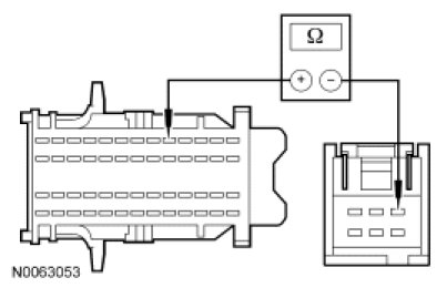
- Measure the resistance between traction control switch C280 pin-1, component side, and pin-6, component side while pressing and releasing the switch.
- Is the resistance greater than 10,000 ohms with the switch released and less than 5 ohms with the switch pressed?
Yes
GO to H4.
No
INSTALL a new traction control switch. TEST the system for normal operation.
-------------------------------------------------
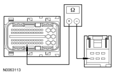
H4 CHECK CIRCUIT CBP35 (YE/GY) FOR AN OPEN
- Ignition OFF.
- Disconnect: Traction Control Switch C280.
- Disconnect: Smart Junction Box (SJB) C2280b.
- Measure the resistance between traction control switch C280-1, circuit CBP35 (YE/GY), harness side and SJB C2280b-9, circuit CBP35 (YE/GY), harness side.
- Is the resistance less than 5 ohms?
Yes
GO to H5.
No
VERIFY SJB fuse 35 (10A) is OK. If OK, REPAIR circuit CBP35 (YE/GY). If not OK, REFER to Wiring Diagrams to identify the possible causes of the circuit short. TEST the system for normal operation.
-------------------------------------------------
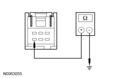
H5 CHECK CIRCUIT CBP35 (YE/GY) FOR A SHORT TO GROUND
- Measure the resistance between traction control switch C280-1, circuit CBP35 (YE/GY), harness side and ground.
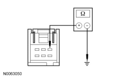
- Is the resistance greater than 10,000 ohms?
Yes
GO to H6.
No
REPAIR circuit CBP35 (YE/GY). TEST the system for normal operation.
-------------------------------------------------
H6 CHECK CIRCUIT CCA15 (YE/GY) FOR AN OPEN
- Disconnect: PCM C175t (Gasoline).
- Disconnect: PCM C1232b (Diesel).
- For gasoline engines, measure the resistance between traction control switch C280-6, circuit CCA15 (YE/GY), harness side and PCM C175t-33, circuit CCA15 (YE/GY), harness side.
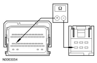
- For diesel engines, measure the resistance between traction control switch C280-6, circuit CCA15 (YE/GY), harness side and PCM C1232b-13, circuit CCA15 (YE/GY), harness side.
- Is the resistance less than 5 ohms?
Yes
GO to H7.
No
REPAIR circuit CCA15 (YE/GY). TEST the system for normal operation.
-------------------------------------------------
H7 CHECK CIRCUIT CCA15 (YE/GY) FOR A SHORT TO GROUND
- Measure the resistance between traction control switch C280-6, circuit CCA15 (YE/GY), harness side and ground.
- Is the resistance greater than 10,000 ohms?
Yes
GO to H8.
No
REPAIR circuit CCA15 (YE/GY). TEST the system for normal operation.
-------------------------------------------------
H8 CHECK THE PCM CONNECTORS
- Ignition OFF.
- Check PCM connector for:
- corrosion.
- pushed-out pins.
- spread terminal.
- Connect the PCM connector and make sure that it is seated correctly.
- Make sure the connector is seated correctly then operate the system and verify the concern is still present.
- Is the concern still present?
Yes
INSTALL a new PCM. TEST the system for normal operation.
No
The system is operating correctly at this time. Concern may have been caused by a loose or corroded connector.
-------------------------------------------------