Glow Plug Sleeve
Glow Plug Sleeve
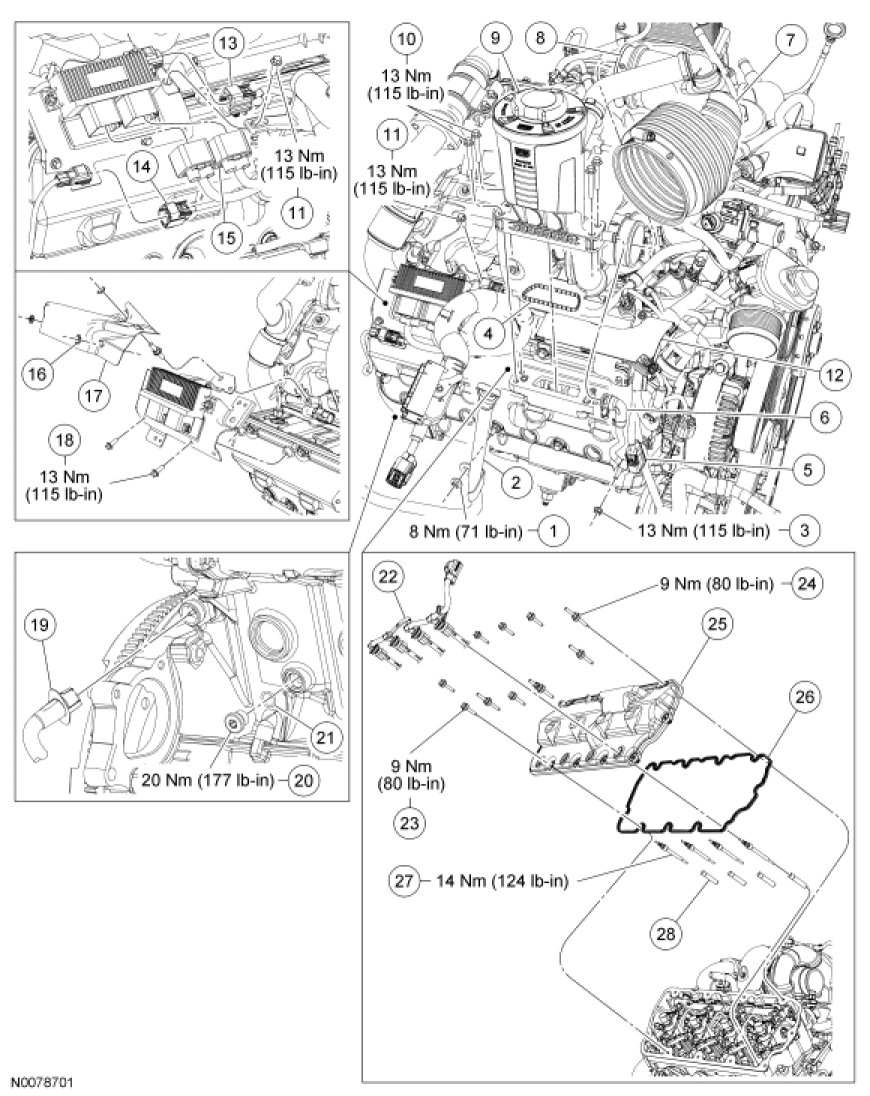
RH Glow Plug Sleeves
LH Glow Plug Sleeves
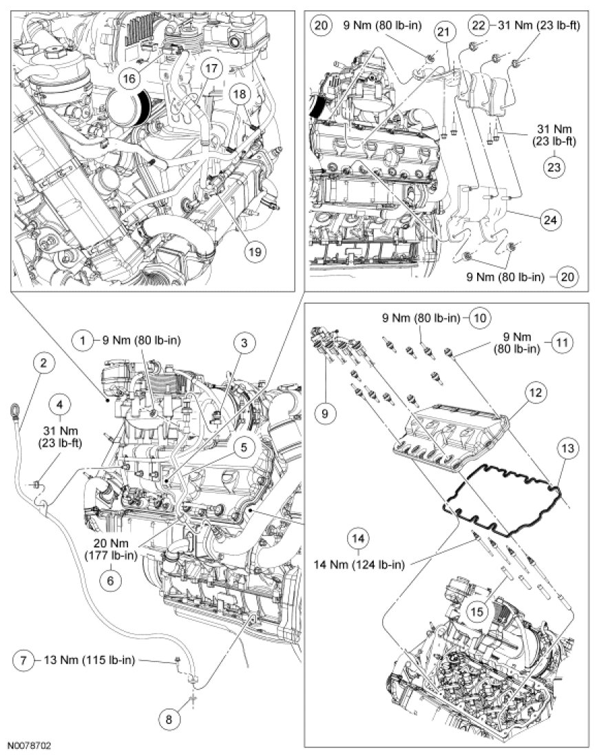
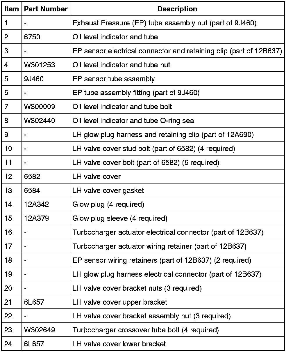
Removal
All vehicles
1. Remove the body.
RH glow plug sleeve
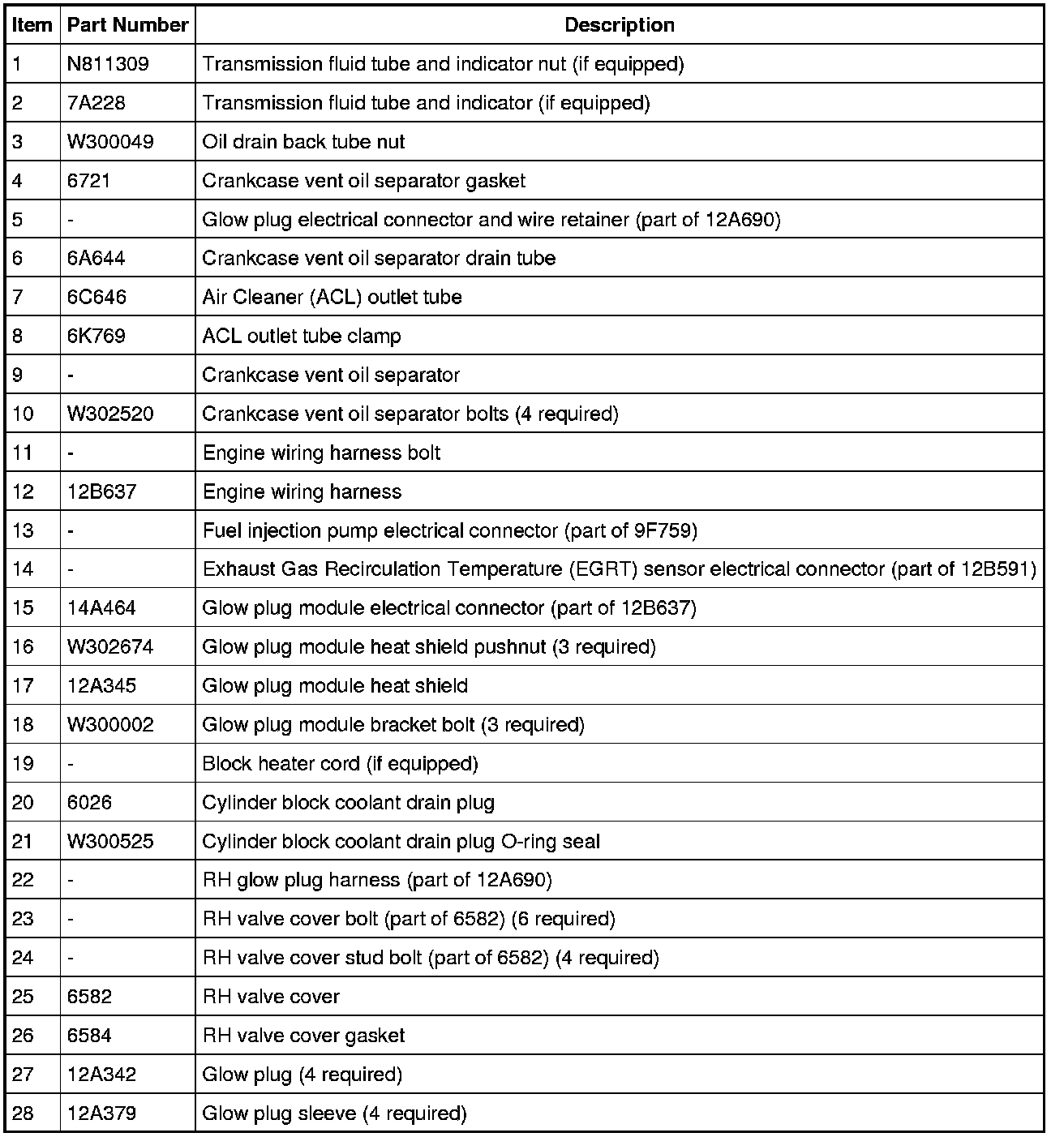
2. If equipped, remove the retaining nut and the transmission fluid indicator and tube.
- Plug or cap the opening.
3. If equipped, disconnect the block heater cord.
4. Remove the starter.
5. Loosen the clamp for the Air Cleaner (ACL) outlet tube.
6. Disconnect the crankcase vent oil separator drain tube.
7. Remove the 4 bolts and the crankcase vent oil separator with the ACL outlet tube.
- Remove and discard the press-in-place gasket.
8. Remove the 3 pushnuts and the glow plug module heat shield.
- Discard the pushnuts.
9. Disconnect the Exhaust Gas Recirculation Temperature (EGRT) sensor electrical connector.
10. Disconnect the glow plug module and fuel injection pump electrical connectors. Detach the electrical connector retainers.
11. Disconnect the pushpin retainer from the glow plug module bracket.
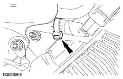
12. Remove the bolt for the engine wiring harness. Position aside the engine wiring harness.
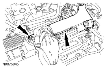
13. Remove the 3 bolts and the glow plug module bracket.
14. Disconnect the glow plug electrical connector and the wire retainer and position aside the engine wiring harness.
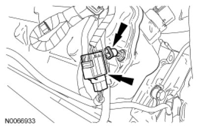
15. NOTICE: Do not disconnect the glow plug electrical connectors before dislodging the seals from the valve cover or the wiring harness may be damaged.
NOTE: Use a tool such as a body bone or trim fork to dislodge the seal. Do not use a screwdriver.
NOTE: Only one glow plug connector shown.
Using an appropriate tool, dislodge the glow plug wiring harness seals from the valve cover and disconnect the retainers.
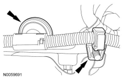
16. Disconnect the glow plug electrical connectors by pulling on the glow plug wiring harness tee (above the seal at each glow plug) and remove the glow plug harness.
17. Remove the nut and position the oil drain back tube aside.
18. NOTE: Mark the location of the stud bolts.
Remove the 4 stud bolts, 6 bolts and valve cover.
- Remove and discard the press-in-place gasket.
- Clean and inspect the sealing surfaces.
LH glow plug sleeve
19. Disconnect the Exhaust Pressure (EP) sensor assembly electrical connector and retaining clip.
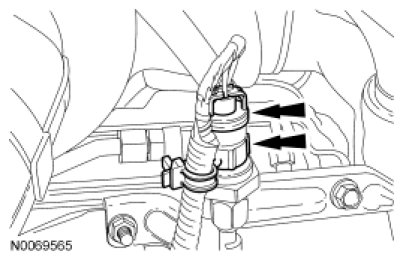
20. Disconnect the glow plug electrical connector and pushpin retainers.
21. Disconnect the turbocharger actuator and pushpin retainer. Position aside the engine wiring.
22. Remove the retaining nut for the oil level indicator and tube bracket.
23. Remove the bolt and the oil level indicator and tube.
- Remove and discard the O-ring seal.
24. NOTICE: Do not disconnect the glow plug electrical connectors before dislodging the seals from the valve cover or the wiring harness may be damaged.
NOTE: Only one glow plug connector shown.
Using an appropriate tool, dislodge the glow plug wiring harness seals from the valve cover and disconnect the retainers.
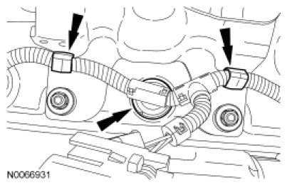
25. Disconnect the glow plug electrical connectors by pulling on the glow plug wiring harness tee (above the seal at each glow plug) and remove the glow plug harness.
26. NOTE: Do not remove the turbocharger crossover, it is equipped with one-time use seals.
Remove the 4 bolts for the turbocharger crossover tube.
27. Disconnect the EP sensor tube assembly fitting.
28. Remove the EP sensor tube assembly nut and the EP sensor tube assembly.
29. Remove the 3 remaining nuts that attach the LH valve cover bracket assembly to the valve cover studs.
30. Remove the 3 nuts that mount the LH valve cover upper bracket to the LH valve cover lower bracket and remove the upper bracket.
31. Remove the LH valve cover lower bracket.
32. NOTE: Mark the location of the stud bolts.
Remove the 4 stud bolts, 6 bolts and valve cover.
- Remove and discard the press-in-place gasket.
- Clean and inspect the sealing surfaces.
All vehicles
33. NOTE: RH side shown, LH side similar.
Remove the cylinder block drain plugs.

34. Remove the glow plug(s).
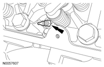
35. NOTICE: Failure to fill the glow plug sleeve with grease will result in damage to the cylinder.
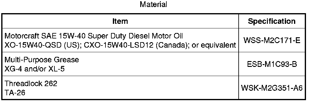
Fill the lower portion of the glow plug sleeve with grease.
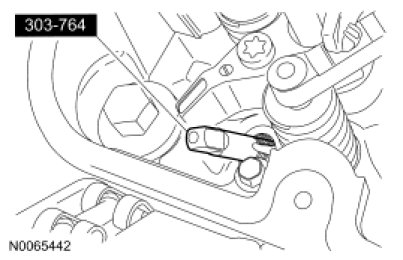
36. NOTE: The glow plug sleeve is made of stainless steel. Lubrication of the glow plug sleeve removal tap is necessary or damage to the tap may occur and excessive force may be needed to get the tap started.
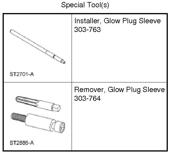
Thread the Glow Plug Sleeve Remover tap into the glow plug sleeve.
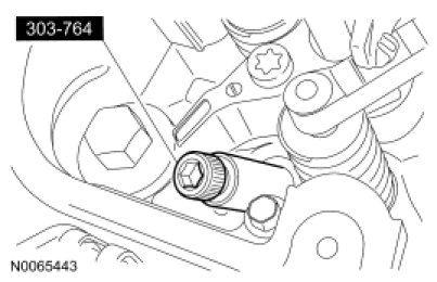
37. Install the Glow Plug Sleeve Remover into the threaded sleeve and tighten. Use a wrench to thread the tool into the sleeve until the sleeve is extracted.
- Discard the glow plug sleeve.
38. Clean the glow plug bore with a stiff wire brush. Use filtered compressed air to remove any foreign material from the glow plug recess.
Installation
All vehicles
1. Verify the glow plug bore is completely clean and dry.
2. Apply threadlock sealant to the new glow plug sleeve in 2 places.

3. Using the Glow Plug Sleeve Installer, install the glow plug sleeve into the glow plug bore until it bottoms.
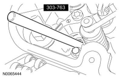
4. Clean the glow plug sleeve after installation with a nylon brush and solvent. Make sure the sealant is cleaned out before it hardens.
5. Install the glow plug(s).
- Tighten to 14 Nm (124 lb-in).
6. NOTE: RH side shown, LH side similar.
NOTE: Lightly lubricate the O-ring seal with clean engine oil.
Install the cylinder block coolant drain plug.
- Tighten to 20 Nm (177 lb-in).
LH glow plug sleeve
7. NOTICE: To prevent engine damage, do not use air-powered tools when installing the valve cover.
NOTE: Alternately tighten the bolts to tighten evenly.
Install new press-in-place gasket. Install the valve cover, 6 bolts and 4 stud bolts.
- Tighten to 9 Nm (80 lb-in).
8. Position the LH valve cover lower bracket on the valve cover studs.
9. NOTE: The LH valve cover bracket assembly must be aligned to the turbocharger crossover tube before assembly nuts are tightened. Do not tighten the nuts at this time.
Position the LH valve cover upper bracket on the lower bracket and valve cover studs, and loosely install the 3 nuts that mount the upper bracket to the lower bracket.
10. Adjust the position of the LH valve cover bracket assembly so the turbocharger crossover tube is level and square to the turbocharger, and tighten the 3 assembly nuts.
- Tighten to 31 Nm (23 lb-ft).
11. Install the 3 nuts that attach the LH valve cover bracket assembly to the valve cover.
- Tighten the LH valve cover bracket nuts to 31 Nm (23 lb-ft).
12. Position the EP sensor tube assembly on the valve cover-to-LH valve cover bracket assembly stud and install the nut.
- Tighten the EP sensor tube assembly nut to 9 Nm (80 lb-in).
13. Connect the EP sensor tube assembly fitting.
- Tighten to 20 Nm (177 lb-in).
14. Install the 4 bolts for the turbocharger crossover tube.
- Tighten to 31 Nm (23 lb-ft).
15. NOTE: Only one glow plug connector shown.
Install the glow plug harness and connect the retainers.
- Make sure the seals are securely seated in the valve cover.
16. NOTE: Install a new O-ring seal prior to installing the oil level indicator and tube.
Install the oil level indicator and tube and the bolt.
- Tighten to 13 Nm (115 lb-in).
17. Install the retaining nut for the oil level indicator and tube bracket.
- Tighten to 31 Nm (23 lb-ft).
18. Position back the engine wiring harness. Connect the turbocharger actuator electrical connector and retainer.
19. Connect the glow plug harness electrical connector and pushpin retainers.
20. Connect the EP sensor assembly electrical connector and retaining clip.
RH glow plug sleeve
21. NOTICE: To prevent engine damage, do not use air-powered tools when installing the valve cover.
NOTE: Alternately tighten the bolts to tighten evenly.
Install new press-in-place gasket. Install the valve cover, 6 bolts and 4 stud bolts.
- Tighten to 9 Nm (80 lb-in).
22. Position the oil drain back tube and install the nut.
- Tighten to 13 Nm (115 lb-in).
23. NOTE: Only one glow plug connector shown.
Install the glow plug harness and connect the retainers.
- Make sure the seals are securely seated in the valve cover.
24. Position the engine wiring harness back. Connect the glow plug electrical connector and the wire retainer.
25. Install the glow plug module bracket and the 3 bolts.
- Tighten to 13 Nm (115 lb-in).
26. Position back the engine wiring harness. Install the bolt for the engine wiring harness.
- Tighten to 13 Nm (115 lb-in).
27. Connect the pushpin retainer to the glow plug module bracket.
28. Attach the electrical connector retainers. Connect the glow plug module and fuel injection pump electrical connectors.
29. Connect the EGRT sensor electrical connector.
30. Position the glow plug module heat shield and install the 3 new pushnuts.
31. Install a new press-in-place gasket. Position the crankcase vent oil separator and the ACL outlet tube on the right valve cover. Install the 4 bolts.
- Tighten to 13 Nm (115 lb-in).
32. Connect the crankcase vent oil separator drain tube.
33. Tighten the clamp for the ACL outlet tube.
- Tighten to 5 Nm (44 lb-in).
34. Install the starter.
35. If equipped, connect the block heater electrical connector.
36. If equipped, install the transmission fluid tube and indicator. Install the nut.
- Tighten to 8 Nm (71 lb-in).
All vehicles
37. Install the body.