Pinpoint Test F: DTC C1414
Anti-Lock Control
Pinpoint Test
Pinpoint Test F: DTC C1414
Refer to wiring Diagram Set 42, Vehicle Dynamic Systems for schematic and connector information. Diagrams By Number
Normal Operation
The ABS module is Rear Wheel Drive (RWD) and Four-Wheel Drive (4WD) specific. The ABS module used in 4WD application includes a G-sensor that detects vehicle movements during an ABS event. The Instrument Cluster (IC) and the ABS module communicate 4WD status along circuit CCF23 (GN/VT).
- DTC C1414 Incorrect Module Design Level - If an ABS module for a RWD vehicle is installed on a 4WD vehicle or if an ABS module for a 4WD vehicle is installed on a RWD vehicle, DTC C1414 will be set. An open circuit, a short to ground or a short to voltage in circuit CCF23 (GN/VT) will also set DTC C1414.
This pinpoint test is intended to diagnose the following:
- Wiring, terminals or connectors
- IC
- ABS module
PINPOINT TEST F: DTC C1414
NOTICE: Use the Flex Probe Kit for all test connections to prevent damage to the wiring terminals. Do not use standard multi-meter probes.
-------------------------------------------------
F1 VERIFY THE ABS MODULE
- Using the ABS module part number, verify that the module installed on the vehicle is the correct one for that application (RWD versus 4WD).
- Is the correct ABS module installed on the vehicle?
Yes
GO to F2.
No
INSTALL the correct ABS module on the vehicle. REFER to Anti-Lock Brake System (ABS) Module Service and Repair. CLEAR the DTCs. CARRY OUT the self-test with the brake pedal not applied.
-------------------------------------------------
F2 CONFIGURE THE IC
- Connect the scan tool.
- Ignition ON.
- Configure the IC. REFER to Programmable Module Installation (PMI) in Information Bus.
- Using the scan tool, clear the ABS module DTCs.
- Ignition OFF.
- Ignition ON.
- Enter the following diagnostic mode on the scan tool: Self Test - ABS Module.
- Does DTC C1414 return?
Yes
For 4WD vehicles, GO to F3.
For RWD vehicles, GO to F8.
No
The concern was caused by an incorrect or incomplete IC configuration.
-------------------------------------------------
F3 CHECK THE 4WD STATUS CIRCUIT
- Verify the correct operation of the 4WD system. If the 4WD system is not operating correctly, it must be repaired before proceeding.
- Ignition OFF.
- Disconnect: IC C220B.
- Measure the voltage between IC C220B-9, circuit CCF23 (GN/VT), harness side and ground.
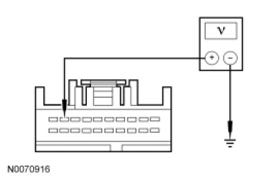
- Is the voltage greater than 10 volts?
Yes
GO to F4.
No
GO to F5.
-------------------------------------------------
F4 CHECK FOR CORRECT IC OPERATION
- Disconnect all IC connectors.
- Check the connectors for:
- corrosion.
- pushed-out pins.
- spread terminals.
- Connect all IC connectors and make sure they seat correctly.
- Operate the system and verify the concern is still present.
- Is the concern still present?
Yes
INSTALL a new IC.
No
The system is operating correctly at this time. Concern may have been caused by a loose or corroded connector. CLEAR the DTCs. REPEAT the self-test with the brake pedal not applied.
-------------------------------------------------
F5 CHECK THE 4WD STATUS CIRCUIT FOR AN OPEN
- Ignition OFF.
- Disconnect: ABS Module C135.
- Measure the resistance between ABS module C135-10, circuit CCF23 (GN/VT), harness side and IC C220B-9, circuit CCF23 (GN/VT), harness side.
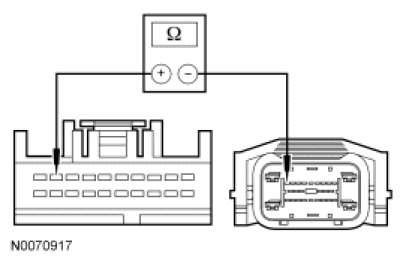
- Is the resistance less than 5 ohms?
Yes
GO to F6.
No
REPAIR circuit CCF23 (GN/VT). CLEAR the DTCs. REPEAT the self-test with the brake pedal not applied.
-------------------------------------------------
F6 CHECK THE 4WD STATUS CIRCUIT FOR A SHORT TO GROUND
- Measure the resistance between ABS module C135-10, circuit CCF23 (GN/VT), harness side and ground.
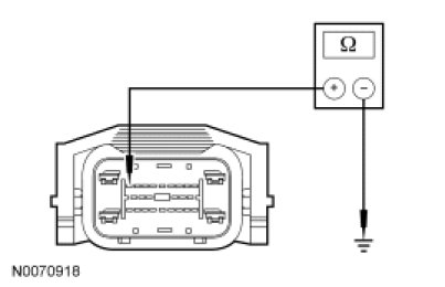
- Is the resistance greater than 10,000 ohms?
Yes
GO to F7.
No
REPAIR circuit CCF23 (GN/VT). CLEAR the DTCs. REPEAT the self-test with the brake pedal not applied.
-------------------------------------------------
F7 CHECK THE 4WD STATUS CIRCUIT FOR A SHORT TO VOLTAGE
- Ignition ON.
- Measure the voltage between ABS module C135-10, circuit CCF23 (GN/VT), harness side and ground.
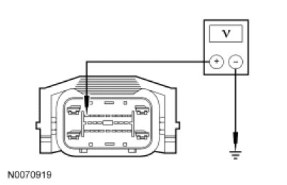
- Is any voltage present?
Yes
REPAIR circuit CCF23 (GN/VT). CLEAR the DTCs. REPEAT the self-test with the brake pedal not applied.
No
GO to F8.
-------------------------------------------------
F8 CHECK FOR CORRECT ABS MODULE OPERATION
- Check ABS module C135 for:
- corrosion.
- pushed-out pins.
- spread terminals.
- Connect: ABS Module C135.
- Make sure the connector seats correctly, then operate the system and verify the concern is still present.
- Is the concern still present?
Yes
INSTALL a new ABS module. REFER to Anti-Lock Brake System (ABS) Module Service and Repair. CLEAR the DTCs. REPEAT the self-test with the brake pedal not applied.
No
The system is operating correctly at this time. Concern may have been caused by a loose or corroded connector. CLEAR the DTCs. REPEAT the self-test with the brake pedal not applied.
-------------------------------------------------