Pinpoint Test C: The Speed Control Does Not Disengage When The Brakes Are Applied
Speed Control
Pinpoint Tests
Pinpoint Test C: The Speed Control Does Not Disengage When The Brakes Are Applied
Refer to wiring Diagram Set 31, Speed Control for schematic and connector information. Diagrams By Number
Normal Operation
The speed control actuator sends a voltage reference signal through circuit CCB15 (BN/GN). The stoplamps provide a ground path that enables speed control operation. When the brake pedal is applied, the voltage goes high and speed control goes into stand-by mode.
Voltage for the speed control servo clutch (internal to the speed control actuator) is supplied by the Smart Junction Box (SJB) to the speed control deactivator switch through circuit CBP26 (BU/WH). The speed control deactivator switch (closed when the brake pedal is not applied) then routes the voltage to circuit CES09 (VT/OG) to the speed control actuator. When the brake pedal is firmly applied, the speed control deactivator switch opens and voltage is no longer supplied to the speed control servo clutch.
This pinpoint test is intended to diagnose the following:
- Wiring, terminals or connectors
- Obstructions to the accelerator pedal or linkage
- Speed control deactivator switch
- Stoplamp switch
- Speed control cable
- Accelerator cable
- Speed control actuator
PINPOINT TEST C: THE SPEED CONTROL DOES NOT DISENGAGE WHEN THE BRAKES ARE APPLIED
NOTICE: Use the correct probe adapter(s) when making measurements. Failure to use the correct probe adapter(s) may damage the connectors.
-------------------------------------------------
C1 CHECK THE SPEED CONTROL CABLE/ACCELERATOR CABLE
- Ignition OFF.
- NOTE: Make sure the floor mat, insulation, wiring harnesses location, and other items do not interfere with the accelerator pedal and linkage.
- Visually inspect the speed control cable connections, the throttle body linkage, and the speed control actuator pulley cover.
- Are the speed control cable connections, the throttle body linkage, and the speed control actuator pulley cover OK?
Yes
GO to C2.
No
INSTALL a new speed control cable or accelerator cable. For a new speed control cable, REFER to Speed Control Cable Service and Repair. TEST the system for normal operation. For a new accelerator cable,
REFER to Throttle Cable/Linkage. TEST the system for normal operation.
-------------------------------------------------
C2 CHECK THE STOPLAMPS FOR CORRECT OPERATION
- Check the stoplamps and high mounted stoplamp for correct operation by firmly applying and releasing the brake pedal.
- Do the stoplamps operate correctly?
Yes
GO to C3.
No
REFER to Lighting and Horns to continue diagnosis of the stoplamps. Testing and Inspection
-------------------------------------------------
C3 CHECK THE SPEED CONTROL DEACTIVATOR CIRCUIT
- Disconnect: Speed Control Actuator C122.
- Ignition ON.
- Measure the voltage between the speed control actuator C122-9, circuit CES09 (VT/OG), harness side and ground while firmly applying the brake pedal.
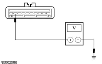
- Is any voltage present?
Yes
GO to C4.
No
INSTALL a new speed control actuator. REFER to Speed Control Actuator Service and Repair. TEST the system for normal operation.
-------------------------------------------------
C4 CHECK THE SPEED CONTROL DEACTIVATOR CIRCUIT FOR A SHORT TO VOLTAGE
- Ignition OFF.
- Disconnect: Speed Control Deactivator Switch C277.
- Ignition ON.
- Measure the voltage between the speed control actuator C122-9, circuit CES09 (VT/OG), harness side and ground.
- Is any voltage present?
Yes
REPAIR the circuit. TEST the system for normal operation.
No
INSTALL a new speed control deactivator switch. REFER to Speed Control Deactivator Switch Speed Control Deactivator Switch. TEST the system for normal operation.
-------------------------------------------------