Pinpoint Test F: The Flash-To-Pass Feature Is Inoperative
Headlamps
Pinpoint Tests
Pinpoint Test F: The Flash-To-Pass Feature Is Inoperative
Refer to wiring Diagram Set 85, Headlamps/Autolamps for schematic and connector information. Diagrams By Number
Normal Operation
The multifunction switch is supplied voltage from the Smart Junction Box (SJB) through circuit SBP23 (WH/RD). When the multifunction switch is placed in the FLASH-TO-PASS position, the voltage is routed to the high beam circuitry.
This pinpoint test is intended to diagnose the following:
- Fuse
- Wiring, terminals or connectors
- Multifunction switch
- SJB
PINPOINT TEST F: THE FLASH-TO-PASS FEATURE IS INOPERATIVE
NOTICE: Use the correct probe adapter(s) when making measurements. Failure to use the correct probe adapter(s) may damage the connector.
-------------------------------------------------
F1 CHECK THE HIGH BEAM OPERATION
- Ignition OFF.
- Place the headlamp switch in the HEADLAMPS ON position.
- Place the multifunction switch in the HIGH BEAM position.
- Do the high beams illuminate?
Yes
GO to F2.
No
Go To Pinpoint Test C. Pinpoint Test C: Both High Beams Are Inoperative
-------------------------------------------------
F2 CHECK FOR VOLTAGE TO THE MULTIFUNCTION SWITCH
- Place the headlamp switch in the OFF position.
- Disconnect: Multifunction Switch C202b.
- Measure the voltage between the multifunction switch C202b-6, circuit SBP23 (WH/RD), harness side and ground.
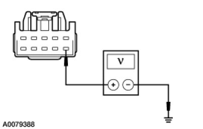
- Is the voltage greater than 10 volts?
Yes
INSTALL a new multifunction switch. TEST the system for normal operation.
No
GO to F3.
-------------------------------------------------
F3 CHECK CIRCUIT SBP23 (WH/RD) FOR AN OPEN
- Disconnect: SJB C2280b.
- Measure the resistance between the multifunction switch C202b-6, circuit SBP23 (WH/RD), harness side and the SJB C2280b-1, circuit SBP23 (WH/RD), harness side.
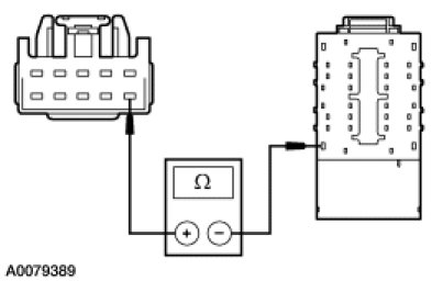
- Is the resistance less than 5 ohms?
Yes
GO to F4.
No
REPAIR the circuit. TEST the system for normal operation.
-------------------------------------------------
F4 CHECK FOR CORRECT SJB OPERATION
- Disconnect all the SJB connectors.
- Check for:
- corrosion
- damaged pins
- pushed-out pins
- Connect all the SJB connectors and make sure they seat correctly.
- Operate the system and verify the concern is still present.
- Is the concern still present?
Yes
INSTALL a new SJB. TEST the system for normal operation.
No
The system is operating correctly at this time. The concern may have been caused by a loose or corroded connector.
-------------------------------------------------