Steps 1-50
5R44E and 5R55E
Transmission
All vehicles
1. Thoroughly clean the transmission case and extension housing in solvent and blow dry with compressed air.
2. Inspect the transmission case for the following:
1. Stripped bolt hole threads.
2. Gasket and mating surfaces for burrs or nicks.
3. Obstructions to vent and fluid passages.
- Cracks or warpage.
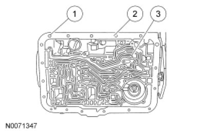
3. Inspect the extension housing for cracks, burrs or warpage.
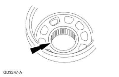
4. Inspect the case bearing for damage. If damage to the case bearing is indicated, install a new case.
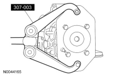
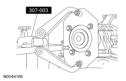
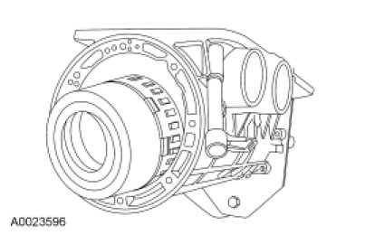
5. Install the Transmission Holding Fixture on the rear of the transmission case.
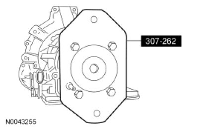
6. Attach the Transmission Holding Fixture as shown.
7. WARNING: Always verify that the lockpin on the bench-mounted holding fixture is correctly secured to help prevent unexpected component rotation. Failure to follow this instruction may result in serious personal injury.
Install the transmission into the Transmission Holding Fixture.
- Rotate the transmission so that the fluid pan rail is facing up.
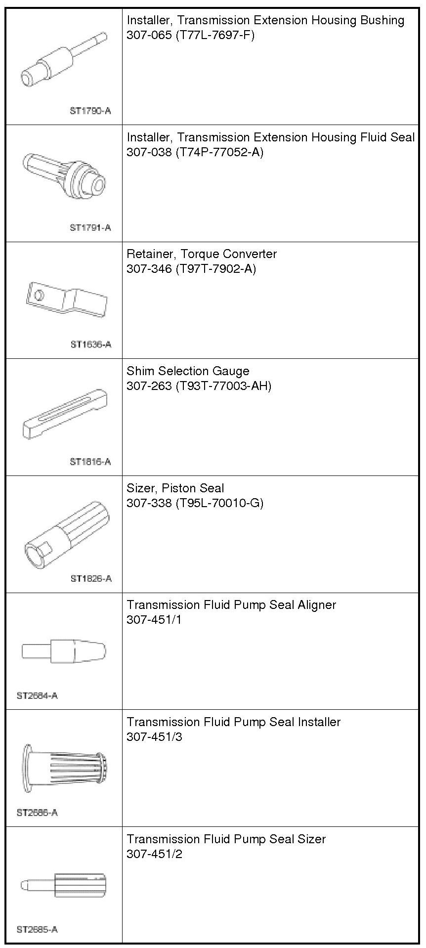
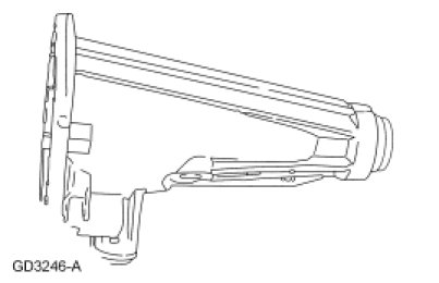
8. Using the Shift Shaft Fluid Seal Installer, install the manual control lever shaft seal.
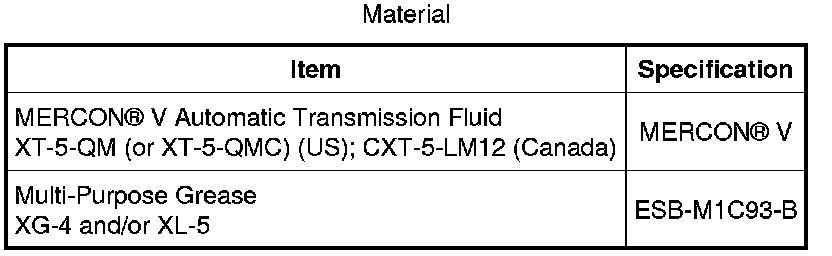
- Lubricate the manual control lever shaft seal with petroleum jelly.

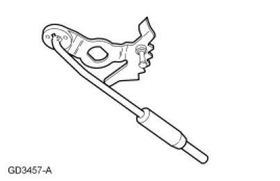
9. Assemble the manual valve inner lever and parking lever actuating rod as shown.
10. Install the manual control lever shaft.
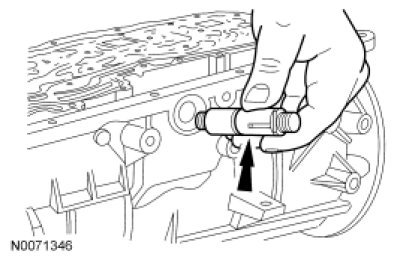
11. NOTICE: Use care not to damage the transmission fluid pan rail surface when installing the retaining pin.
NOTE: Align the manual control lever shaft alignment groove with the manual control lever shaft spring pin bore in the transmission case.
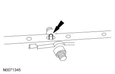
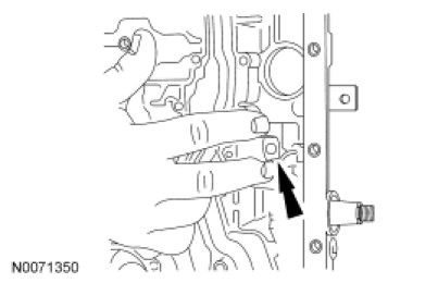
Install the manual control lever shaft spring pin.
- Tap the manual control lever shaft spring pin into the transmission case.
12. NOTE: Align the flats on the manual valve inner lever with the flats on the manual control lever shaft.
Install the manual valve inner lever and parking lever actuating rod on to the manual control lever shaft.
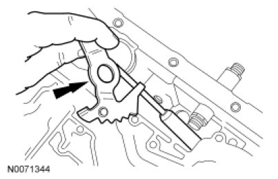
13. NOTICE: To avoid damage, do not allow the wrench to strike the manual valve inner lever pin.
Install the manual valve inner lever nut on the manual control lever shaft.
- Tighten to 48 Nm (35 lb-ft).
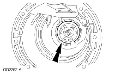
14. NOTE: The tabs on the No. 11 output shaft thrust washer point into the case. Make sure the thrust washer is correctly seated.
Install the No. 11 output shaft thrust washer.
- Coat the output shaft thrust washer with petroleum jelly.
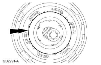
15. Install the park gear.
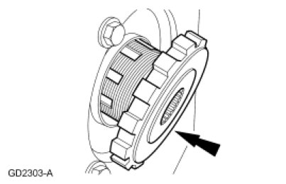
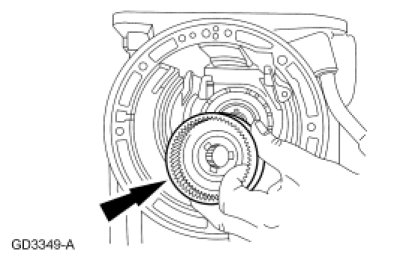
16. Install the low/reverse brake drum.
- Rotate the low/reverse brake drum clockwise to install.
17. If not already installed during subassembly, install the No. 10B needle bearing onto the output shaft ring gear and hub assembly.
- Coat the needle bearing with petroleum jelly.
18. Install the output shaft through the output shaft park gear.
19. Install the output shaft ring gear and output shaft hub.
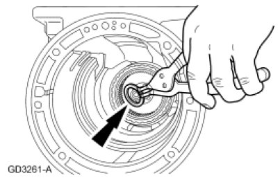
20. NOTE: Always install a new output shaft retaining ring.
Install a new output shaft retaining ring.
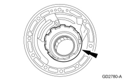
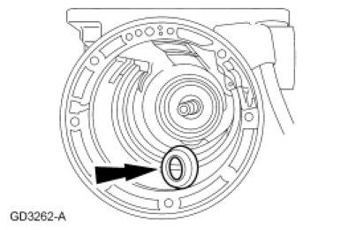
21. NOTE: Install the output shaft sleeve with the cone facing up.
Install the output shaft sleeve.
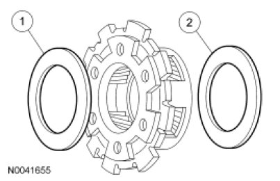
22. Install low/reverse planetary carrier needle bearings.
1. Install the No. 8 low/reverse planetary carrier needle bearing on the front face of the low/reverse planetary.
2. Install the No. 9 low/reverse planetary carrier needle bearing on the rear face of the low/reverse planetary.
- Coat the No. 8 low/reverse planetary carrier needle bearing and No. 9 low/reverse planetary carrier needle bearing with petroleum jelly.
23. NOTE: Make sure needle bearings stay in place.
Install the low/reverse planetary assembly with No. 8 and No. 9 low/reverse planetary carrier needle bearings into the output shaft ring gear.
24. NOTE: The low/reverse brake drum must be pulled forward to install the low/reverse planet retaining ring.
Install the low/reverse retaining ring into the low/reverse brake drum groove.
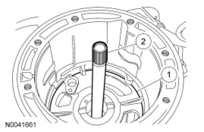
25. NOTE: Make sure band is resting on the 2 anchor pins in the case.
Install the low/reverse band over the low/reverse brake drum.
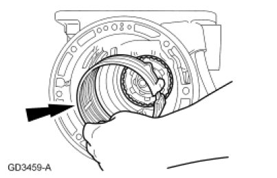
26. Temporarily install the low/reverse band servo piston and rod to hold the low/reverse band in position.
27. Install the previously assembled forward geartrain assembly.
28. WARNING: Always verify that the lockpin on the bench-mounted holding fixture is correctly secured to help prevent unexpected component rotation. Failure to follow this instruction may result in serious personal injury.
Rotate the transmission assembly so that the converter housing surface is facing up.
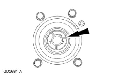
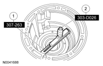
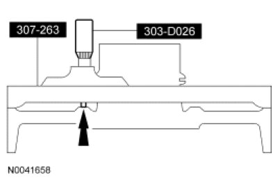
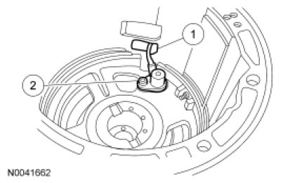
29. Select the No. 4 intermediate brake drum thrust bearing as follows:
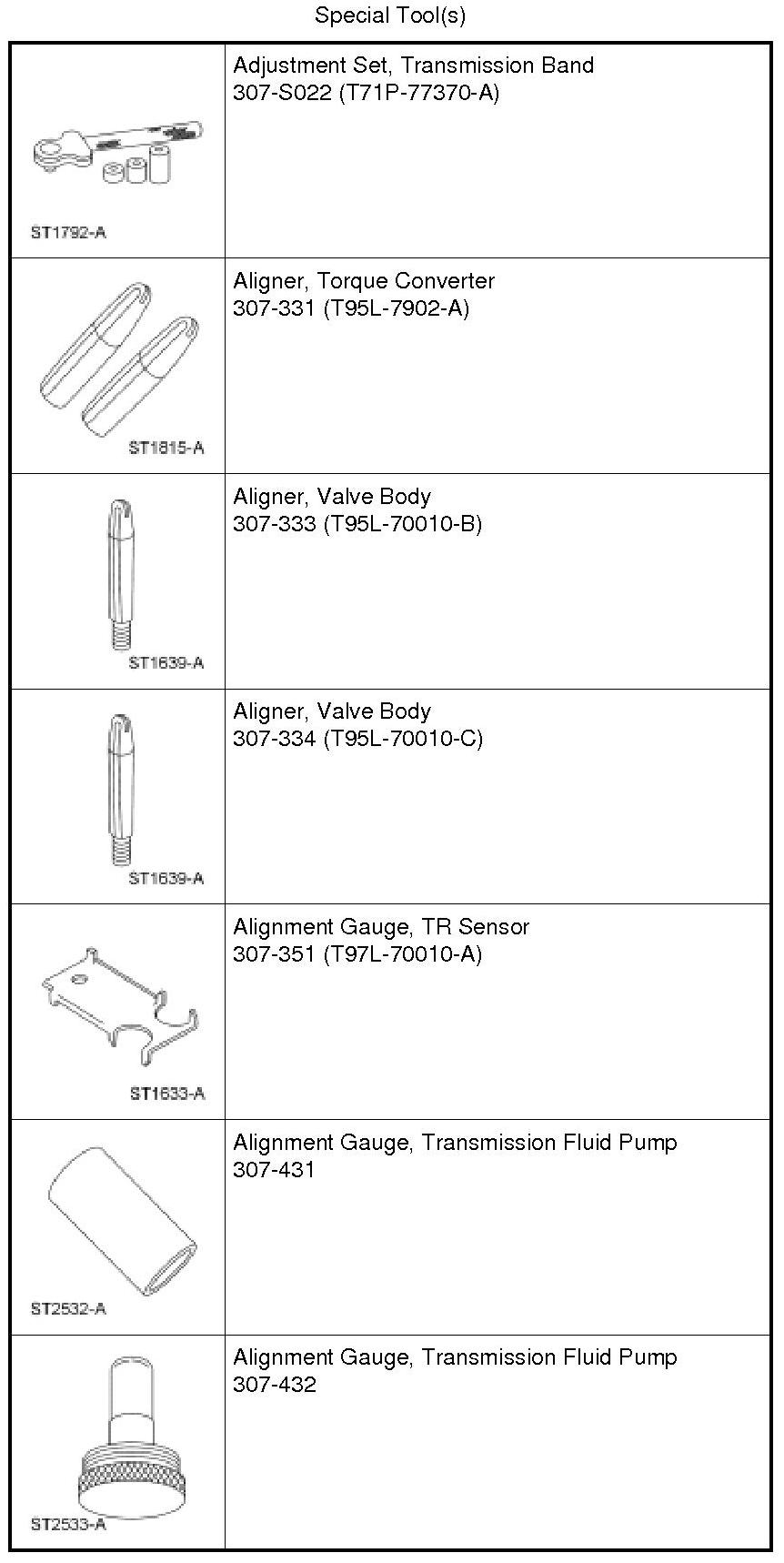
1. Install the Shim Selection Gauge on the case assembly shoulder.
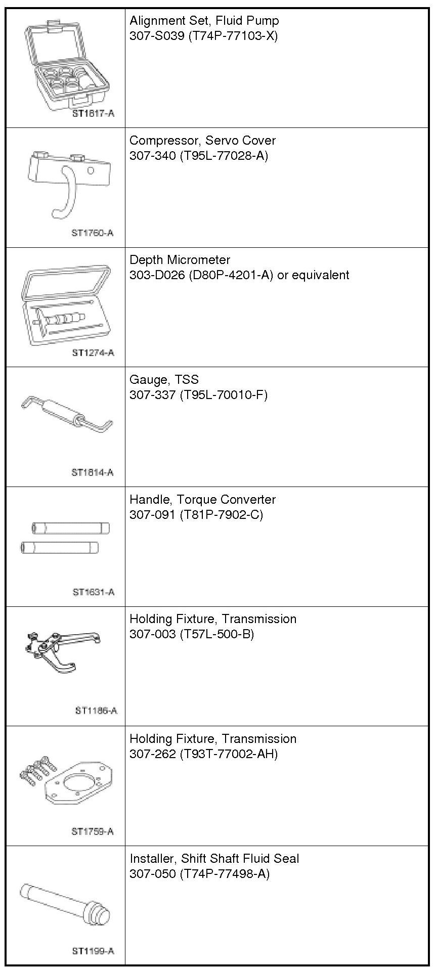
2. Set the Depth Micrometer on top of the Shim Selection Gauge as shown.
30. Calculate the thrust bearing thickness.
- Extend the Depth Micrometer probe until it contacts the intermediate brake drum thrust bearing surface. Record the reading. This is dimension A.
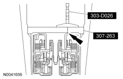
31. Place the Depth Micrometer on the opposite side of the Shim Selection Gauge and repeat the measurement. This is dimension B.
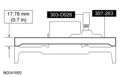
32. Add dimension A and B, divide the total of A and B by 2. Then subtract the Shim Selection Gauge thickness 17.78 mm (0.7 in). Record this reading as dimension C.
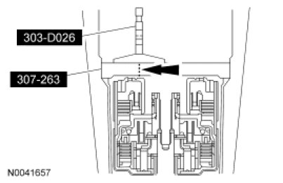
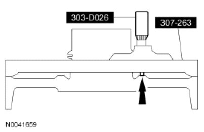
33. Place the Shim Selection Gauge across the center support. Place the Depth Micrometer on the top of the Shim Selection Gauge.
- Extend the Depth Micrometer probe until it makes contact with the center support thrust bearing surface. Record this reading as dimension D.
34. Place the Depth Micrometer on the opposite side of the Shim Selection Gauge.
- Extend the Depth Micrometer probe until it makes contact with the center support thrust bearing surface. Record this reading as dimension F.
35. Add dimensions D and F, divide the total of D and F by 2. Subtract the Shim Selection Gauge thickness 17.78 mm (0.7 in) dimension E. The result is dimension G.
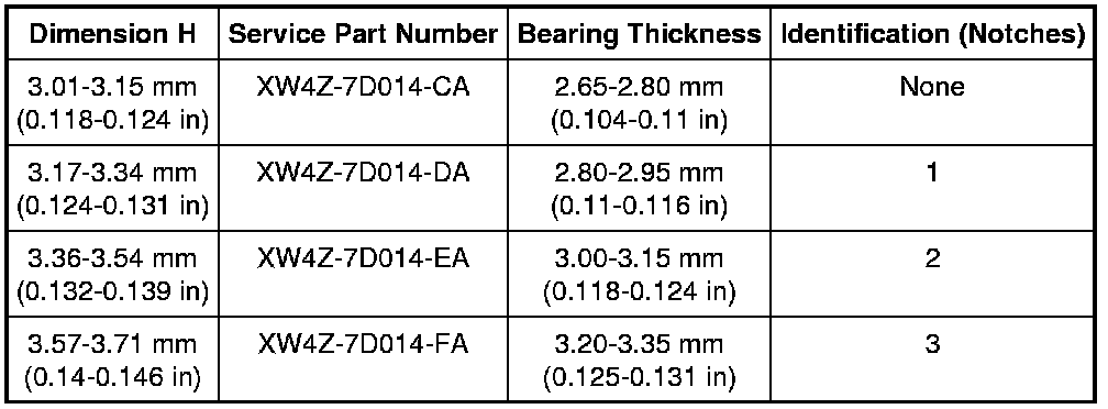
36. Add dimensions C and G. This total is dimension H. Use the following chart to select the correct No. 4 thrust bearing. Reference end play is 0.20-0.54 mm (0.008-0.021 in).
37. Install the intermediate servo actuating lever.
38. NOTE: The intermediate band lever shaft is shorter than the front band lever shaft.
Install the intermediate band actuating lever shaft through the intermediate servo actuating lever.
39. Install the intermediate band apply strut on the intermediate servo actuating lever.
40. NOTE: Make sure that the intermediate apply strut is aligned with the band notch.
Install the intermediate band.
41. NOTE: Use the intermediate band adjusting screw as a temporary alignment guide.
NOTE: The intermediate and front band anchor struts and band adjustment screws are the same.
Install the intermediate band anchor strut and the intermediate band adjustment screw.
42. Install the No. 4 selected intermediate brake drum thrust washer on the center support.
- Coat the intermediate brake drum thrust washer with petroleum jelly.
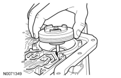
43. NOTICE: Do not apply pressure to the center support while installing. Damage to sealing rings may result.
NOTE: Align the center support screw hole with correct case hole.
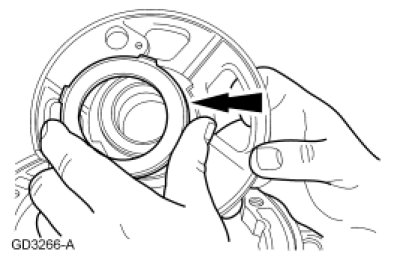
Install the center support.
1. Position the center support into the intermediate brake and direct clutch drum.
2. Temporarily insert the input shaft and gently wiggle it until the center support is seated against the case shoulder, then remove the input shaft.
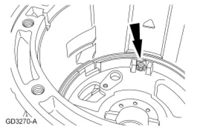
44. NOTE: Install the center support retaining ring with the tapered side facing up.
NOTE: Make sure the notch opening is not obstructed by the center support retaining ring.
Install the center support retaining ring.
1. Position the center support retaining ring with the tapered side facing up.
2. Install the center support retaining ring so that the notch opening is not obstructed.

45. Install the center support locknut and cage.
46. Loosely install the center support-to-case cap screw.
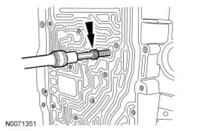
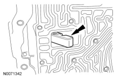
47. NOTICE: Carefully route the Turbine Shaft Speed (TSS) sensor connector and wiring harness through the opening in the case. Do not damage the wiring.
NOTE: Route Turbine Shaft Speed (TSS) sensor electrical connector and wiring through transmission case opening.
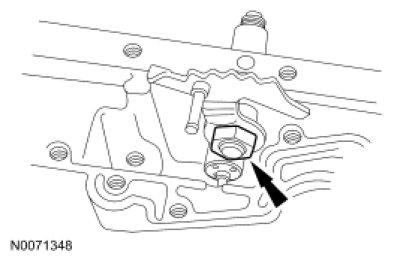
Install the TSS sensor.
1. Install the TSS sensor.
2. Install the TSS sensor screw.
- Tighten to 10 Nm (89 lb-in).
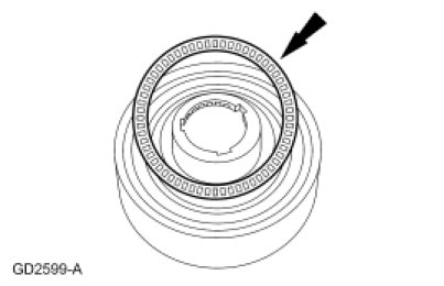
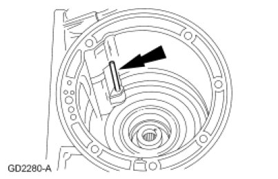
48. NOTE: Use only the No. 3 center shaft thrust bearing.
NOTE: The No. 3 center shaft thrust bearing has no notches on the outer race.
Install the No. 3 center shaft thrust bearing.
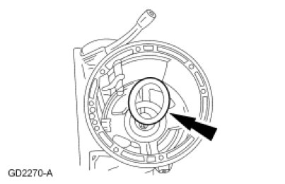
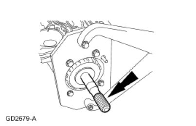
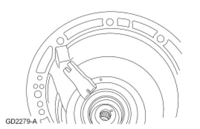
49. NOTICE: Do not bend the trigger wheel.
Install the Overdrive (O/D) planetary and One-Way Clutch (OWC) assembly.
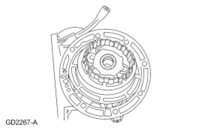
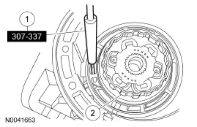
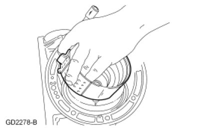
50. NOTE: The trigger wheel triggering window should pass over the thin blade of the TSS Gauge. If it does not, a new overdrive planetary carrier and trigger wheel must be installed.
Using the TSS Gauge, check the TSS sensor air gap.
1. Place the thin blade of the TSS Gauge over the TSS sensor.
2. Rotate the trigger wheel and repeat checks for all windows.