Steps 51-99
5R44E and 5R55E
Transmission
All vehicles
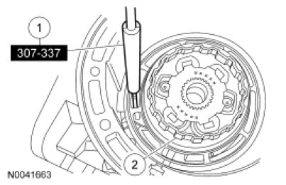
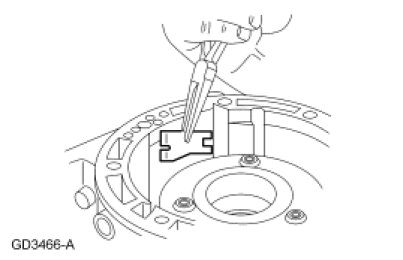
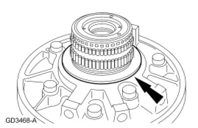
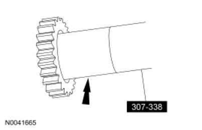
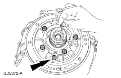
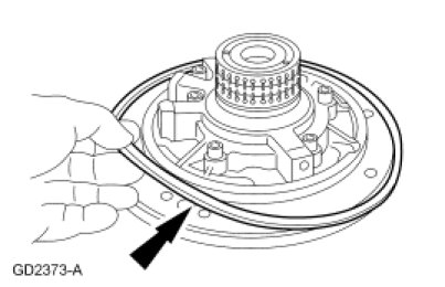
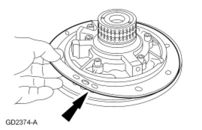
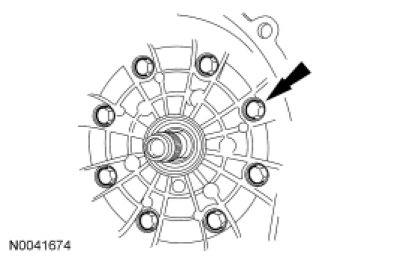
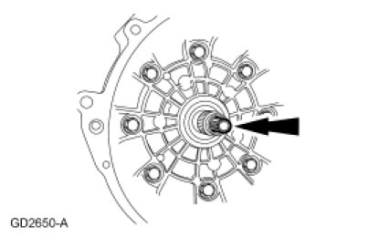
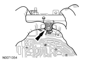
51. NOTE: The trigger wheel triggering window should not pass over the thick blade of the TSS Gauge. If it does, a new overdrive planetary carrier and trigger wheel must be installed.
Using the TSS Gauge, check the TSS sensor air gap.
1. Place the thick blade of the TSS Gauge over the TSS sensor.
2. Rotate the trigger wheel and repeat checks for all windows.
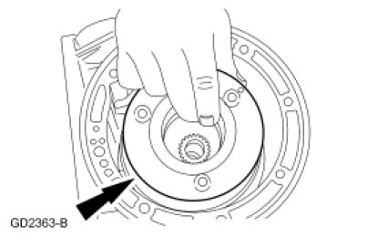
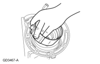
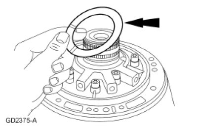
52. NOTE: Align the clutch plates and front adapter gear.
Install the front brake drum and coast clutch drum assembly.
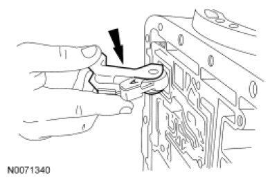
53. Install the front servo band lever and front band lever-to-case bracket into the transmission case.
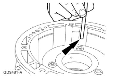
54. NOTE: The front band lever shaft is longer than the intermediate band actuating lever shaft.
Install the front band actuating lever shaft through the front servo band lever.
55. Install the front band apply strut.
56. NOTE: If the front band is reused, it must be installed in its original position.
Install the front band over the front brake and coast clutch drum.
57. NOTE: Use the band adjustment screw as a temporary alignment guide.
Install the front band anchor strut.
58. Install the front band adjusting screw.
59. NOTE: Make sure that the pump body is seated against the thrust washer and the front brake and coast clutch drum. The pump body must be below the level of the case gasket surface.
NOTE: The tabs on the washer go into the pump face.
Carry out the front end play check procedure as follows:
- Coat the No. 1 fluid pump inlet thrust washer with petroleum jelly.
- Install the No. 1 fluid pump inlet thrust washer on the rear of the fluid pump and place the pump into position in the case.
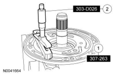
60. NOTE: The Shim Selection Gauge must rest on the gasket surface.
Measure the front end play clearance.
1. Place the Shim Selection Gauge across the case.
2. Insert the Depth Micrometer and extend the Depth Micrometer probe until it contacts the fluid pump face.
- Read the measurement and subtract the Shim Selection Gauge thickness 17.78 mm (0.7 in). This is dimension A.
- Repeat the measurement at the opposite side of the transmission case. This is dimension B.
- Add dimensions A and B together and divide by 2. This is front end clearance, dimension C.
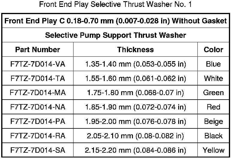
61. NOTE: If the average front end clearance is below the specification, choose a thinner washer. If the average is above the specification, choose a thicker washer.
NOTE: The front end play specification is 0.18-0.70 mm (0.007-0.027 in).
Use dimension C and the chart below to select the correct thickness fluid pump inlet thrust washer (No. 1).
62. NOTE: Make sure that the pump body is seated against the thrust washer and the front brake and coast clutch drum. The pump body must be below the level of the case gasket surface.
NOTE: The tabs on the washer go into the pump face.
Remove the pump and install the No. 1 thrust washer onto the pump. After installing selected front pump thrust washer No. 1, repeat the front end play check. Make sure the end play is correct, then remove the pump for assembly.
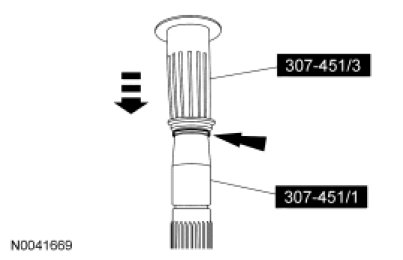
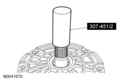
63. Install a new O-ring seal in the fluid pump drive gear.
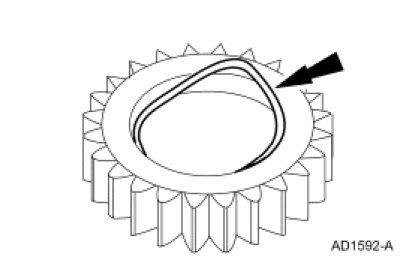
64. NOTE: Lubricate the Piston Seal Sizer with multi-purpose grease.
Install the fluid pump drive gear on the Piston Seal Sizer to seat the O-ring seal. Remove the tool.
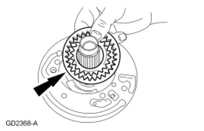
65. NOTICE: The chamber on the inside edge of the small gear must be up when in the pump housing gear pocket. The dimple on the larger gear must be down when in the pump housing gear pocket. Incorrect installation can result in transmission damage.
Install the pump gears into the fluid pump housing. Apply multi-purpose grease to the pump gear to prevent scoring at start-up.
66. NOTE: Make sure the holes in the plate line up with the holes in the pump.
Install the fluid pump adapter plate.
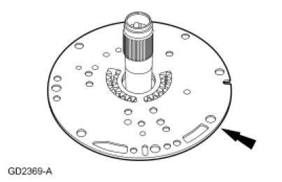
67. NOTE: Do not allow the pump gears to come out of the pump housing pocket.
NOTE: The notch on the outside of the adapter plate will be at the 9 o'clock position relative to the converter housing.
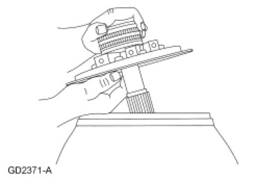
Install the fluid pump on the converter housing.
- Hold the fluid pump adapter plate against the pump housing. Turn the pump and adapter plate over and place on the converter housing.
68. Loosely install the fluid pump screws.
69. NOTICE: The Transmission Fluid Pump Alignment Gauges and the Fluid Pump Alignment Set must be used to correctly align the transmission fluid pump to the transmission fluid adapter plate. This will prevent seal leakage, gear noise, broken gears and bushing failure.
Align the transmission fluid pump to the transmission fluid pump adapter plate and select the gauge from the Fluid Pump Alignment Set that is the snuggest fit when placed over the fluid pump.
70. Thread the Fluid Pump Alignment Set over Transmission Fluid Pump Alignment Gauges and then over the fluid pump until it bottoms out in the fluid pump gear pocket.
71. Tighten the fluid pump screws in a star pattern and remove the pump alignment handle.
- Tighten to 26 Nm (19 lb-ft).
72. Install a new fluid pump seal ring.
- Coat the fluid pump seal ring with petroleum jelly.
73. NOTE: Make sure the fluid pump seal ring is installed on the housing and pump assembly.
Install a new fluid pump gasket.
- Hold the fluid pump gasket in place with petroleum jelly.
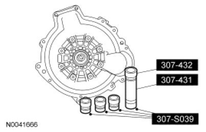
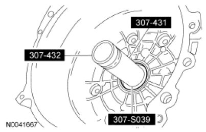
74. NOTICE: Be careful not to overstretch the seal ring past the seal ring groove or damage to the seal will occur.
Using the Transmission Fluid Pump Seal Installer and the Transmission Fluid Pump Seal Aligner, install the fluid pump seal ring.
75. NOTE: Verify correct seal installation. Make sure seal grooves are clean and free of burrs.
Verify that the seal is installed correctly.

76. NOTICE: Failure to correctly size the seal will damage the seal when the torque converter is installed.
Using the Transmission Fluid Pump Seal Sizer, size the seal to the correct size. Leave the Transmission Fluid Pump Seal Sizer on the seal for 2 minutes to obtain the correct seal size.
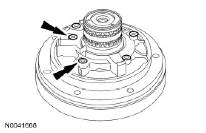
77. Install the selected No. 1 fluid pump thrust washer.
- Coat the fluid pump thrust washer with petroleum jelly.
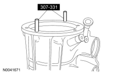
78. Install the Torque Converter Aligners into the transmission case.
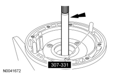
79. NOTE: The splines on the ends of the input shaft are not the same length. The shorter splines go into the assembly.
Install the input shaft.
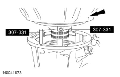
80. NOTE: Make sure that the No. 1 fluid pump inlet thrust washer selective thrust washer, fluid pump gasket and the fluid pump-to-case O-ring seal remain in the correct position throughout this step.
Install the fluid pump and converter housing onto the case.
81. NOTE: Lubricate the O-ring seals on the converter housing screws.
Remove the Torque Converter Aligners. Install the new converter housing-to-case screws. Tighten the screws in a star pattern.
- Tighten to 47 Nm (35 lb-ft).
82. Remove the input shaft.
83. WARNING: Always verify that the lockpin on the bench-mounted holding fixture is correctly secured to help prevent unexpected component rotation. Failure to follow this instruction may result in serious personal injury.
Rotate the transmission assembly so the fluid pan rails are facing up.
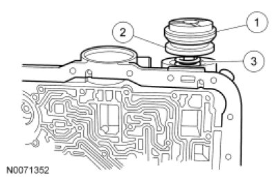
84. Assemble the front servo assembly.
1. Install the front servo cover O-ring seal on the front servo cover. Coat the front servo cover O-ring seal with petroleum jelly.
2. Install the front servo piston into the front servo cover.
3. Install the front servo piston spring on the front servo piston.
85. NOTICE: Do not damage the front servo-to-case O-ring seal during installation.
NOTICE: Do not press the front servo cover and O-ring seal past the relief hole in the case or O-ring seal damage can occur.
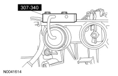
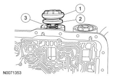
Using the Servo Cover Compressor, install the front servo assembly into the case and install the front servo cover retaining ring.
86. Assemble the intermediate servo assembly.
1. Install the intermediate servo cover O-ring seal on the intermediate servo cover. Coat the intermediate servo cover O-ring seal with petroleum jelly.
2. Install the intermediate servo piston into the intermediate servo cover.
3. Install the intermediate servo piston spring on the intermediate servo piston.
87. NOTICE: Do not damage servo cover-to-case O-ring seal during installation.
NOTICE: Do not press the intermediate servo cover and O-ring seal past the relief hole in the case or O-ring seal damage can occur.
Using the Servo Cover Compressor, install the intermediate servo assembly into the case and install the intermediate servo cover retaining ring.
88. NOTE: Do not allow front band adjustment screw to back out. The band strut may fall out of position.
NOTE: Install, but do not tighten, a new locknut on the band adjustment screw. Apply petroleum jelly to the locknut seal.
Install a new locknut on the band adjustment screw.
89. NOTE: The front servo must be installed prior to band adjustment.
NOTE: The wrench will click at the specified torque.
Using the Transmission Band Adjustment Set, tighten the front band adjustment screw.
- Tighten to 14 Nm (124 lb-in).
- Then, back off the front band adjustment screw exactly 2 turns and hold that position.

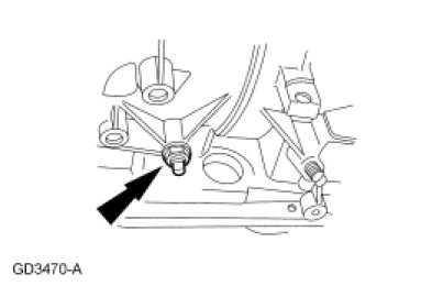
90. Tighten the front band locknut.
1. Hold the front band adjustment screw stationary.
2. Tighten the front band locknut.
- Tighten to 54 Nm (40 lb-ft).

91. NOTE: Do not allow the intermediate band adjusting screw to back out. The band strut could fall out of position.
NOTE: Install, but do not tighten, a new locknut on the band adjustment screw. Apply petroleum jelly to the locknut seal.
Install a new nut on the band adjustment screw.
92. NOTE: The intermediate servo must be installed prior to band adjustment.
NOTE: The wrench will click at the specified torque.
Using the Transmission Band Adjustment Set, tighten the front band adjustment screw.
- Tighten to 14 Nm (124 lb-in).
- Then, back off the front band adjustment screw exactly 2 turns and hold that position.

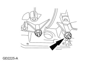
93. Tighten the intermediate band locknut.
1. Hold the intermediate band adjustment screw stationary.
2. Tighten the intermediate band locknut.
- Tighten to 54 Nm (40 lb-ft).

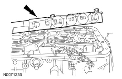
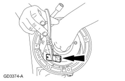
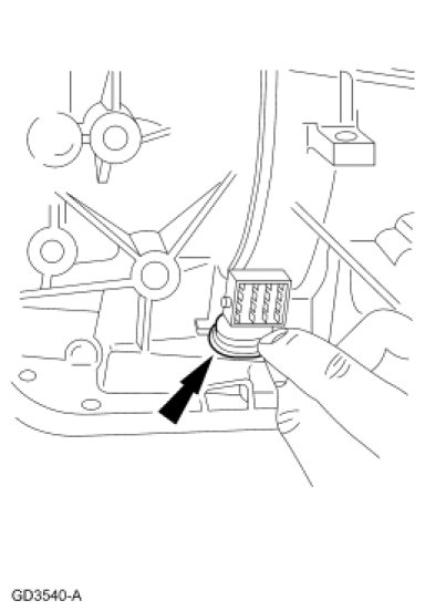
94. NOTE: Install new O-ring seals on the 16-pin electrical connector. Coat the O-ring seals with petroleum jelly.
NOTE: Make sure that the tab is in the lock position.
Position the transmission case 16-pin electrical connector into the case bore.
- Press the transmission case 16-pin electrical connector through the case until a click is heard.
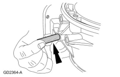
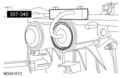
95. NOTICE: Do not overstretch the retaining spring. Overstretching may damage the spring.
Install the 16-pin electrical connector retaining spring.
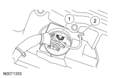
96. NOTE: Align the slot on the TSS sensor electrical connector with the slot in the 16-pin electrical connector.
Install the TSS sensor electrical connector into the transmission case 16-pin electrical connector.
1. Connect the TSS sensor electrical connector.
2. Insert the TSS sensor electrical connector wires into the retaining slot in the 16-pin electrical connector.
97. Tighten the center support screw.
- Tighten to 11 Nm (97 lb-in).

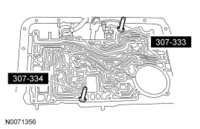
98. Install the Valve Body Aligners into the transmission case.
99. NOTE: Make sure main control valve body gasket is aligned.
NOTE: Make sure that the manual valve is correctly aligned with the manual valve inner pin when the main control valve body is installed.
Position the main control valve body into the transmission case.