Engine - Installation
Engine
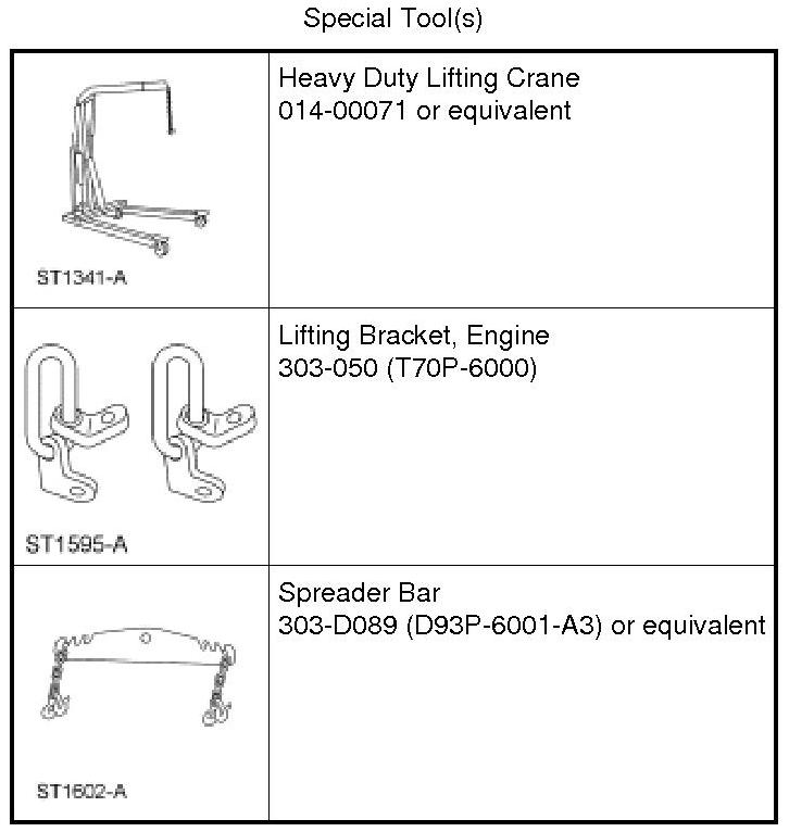

Installation
All vehicles
NOTICE: If used as a leverage device, the fuel rail may be damaged. Care must be taken when working around the fuel rail.
1. Install the engine, remove the Heavy Duty Lifting Crane and the Spreader Bar.
2. Remove the Engine Lifting Brackets.
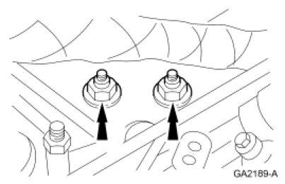
3. Install the 2 LH engine insulator nuts.
- Tighten to 110 Nm (81 lb-ft).
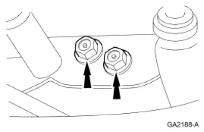
4. Install the 2 RH engine insulator nuts.
- Tighten to 110 Nm (81 lb-ft).
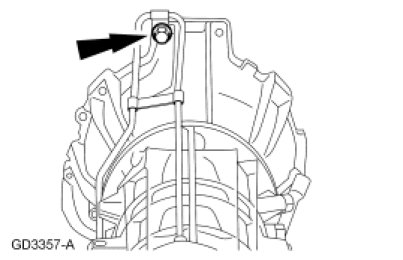
5. NOTE: Automatic transmission shown, manual transmission similar.
Install the 8 transmission-to-engine bolts.
- Tighten to 47 Nm (35 lb-ft).
6. If equipped with A/C, position the A/C tube bracket and install the nut.
- Tighten to 20 Nm (177 lb-in).
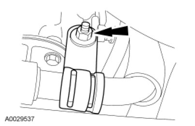
7. NOTE: LH shown, RH similar.
Install the 4 exhaust manifold-to-dual converter Y-pipe nuts.
- Tighten to 40 Nm (30 lb-ft).
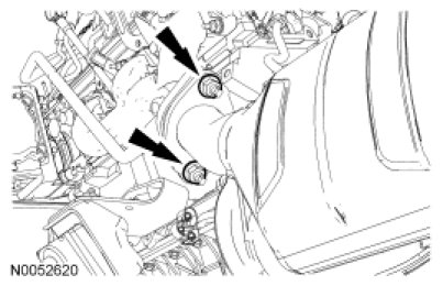
8. Connect the RH Heated Oxygen Sensor (HO2S) electrical connector.
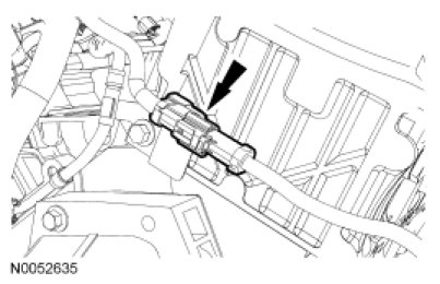
9. Connect the LH HO2S electrical connector.
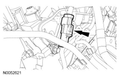
10. Install a new engine oil filter.
- Tighten to 13 Nm (115 lb-in).
11. Route the transmission wiring harness from the top of the engine to the transmission.
12. Attach the wiring harness to the crossmember and connect the electrical connector.
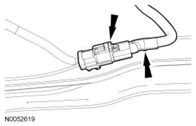
Vehicles equipped with a manual transmission
13. Connect the transmission and LH Catalyst Monitor Sensor (CMS) electrical connectors and attach the wiring harness retainers.
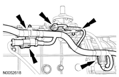
14. Route the wiring harness over the transmission and position the bracket on the stud. Install the nut and connect the RH CMS electrical connector.
- Tighten to 10 Nm (89 lb-in).
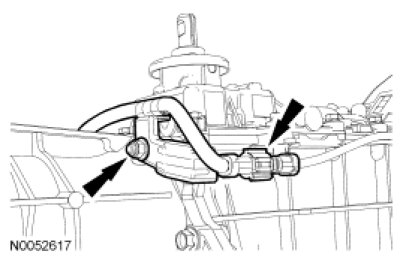
Vehicles equipped with an automatic transmission
15. NOTICE: Rotating the crankshaft pulley bolt counterclockwise could cause a reduction in clamp load on the crankshaft pulley and timing sprocket, which may cause severe engine damage.
Install the 4 torque converter nuts.
- Tighten to 47 Nm (35 lb-ft).
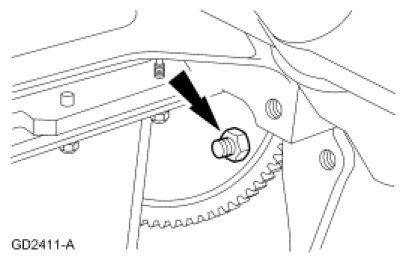
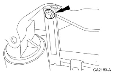
16. Position the transmission cooling tube bracket and install the bolt.
- Tighten to 47 Nm (35 lb-ft).
17. Connect the transmission and LH Catalyst Monitor Sensor (CMS) electrical connectors. Attach the wiring harness retainers.
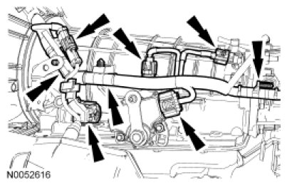
18. Route the wiring harness over the transmission and position the bracket on the stud. Install the nut and connect the RH CMS electrical connector.
- Tighten to 10 Nm (89 lb-in).
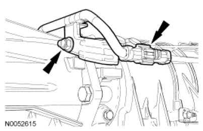
19. Position the transmission level indicator tube and install the nut.
- Tighten to 23 Nm (17 lb-ft).
All vehicles
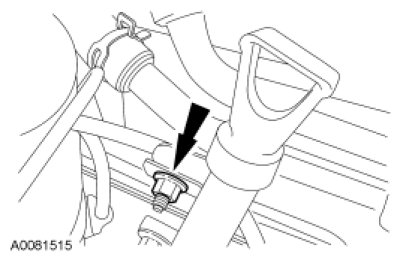
20. NOTE: Rear Wheel Drive (RWD) vehicle shown, Four-Wheel Drive (4WD) vehicle similar.
Install the engine wiring harness bracket and bolt and connect the Engine Oil Pressure (EOP) switch electrical connector.
- Tighten to 10 Nm (89 lb-in).
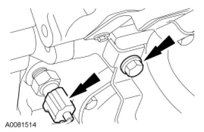
21. Install the starter motor.
22. Connect the heater hose.
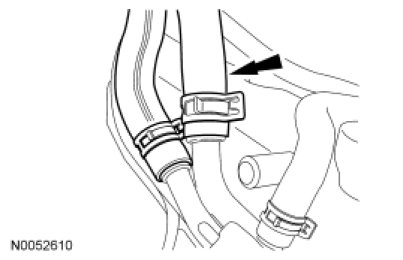
23. Connect the heater hose.
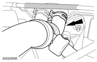
24. Position the vacuum hose harness and connect the 2 vacuum hoses (1 shown). Install the crankcase breather hose.
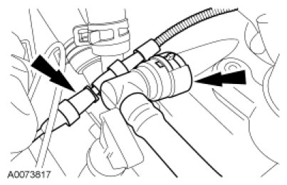
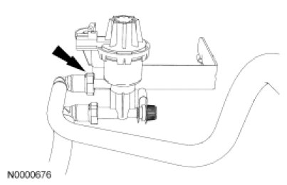
25. Connect the vapor hose to the purge valve.
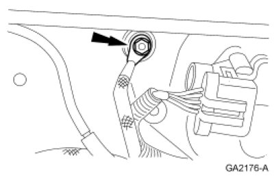
26. Position the ground wire and install the nut.
- Tighten to 10 Nm (89 lb-in).
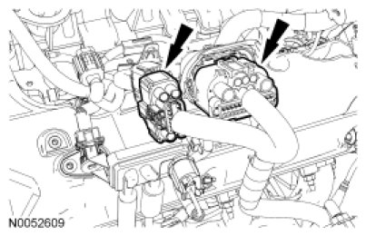
27. Connect the 2 engine wiring harness electrical connectors.
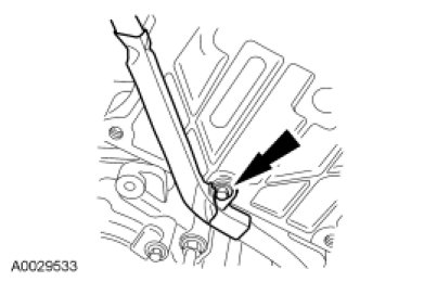
28. Position the wiring harness and install the bolt.
- Tighten to 10 Nm (89 lb-in).
29. Connect the generator wiring and install the generator terminal nut.
- Tighten to 8 Nm (71 lb-in).
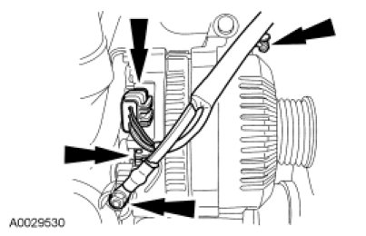
30. Position the A/C compressor and power steering bracket and install the 4 bolts.
- Tighten to 42 Nm (31 lb-ft).

31. NOTE: The battery is removed for clarity.
Connect the power steering return hose to the power steering fluid reservoir.
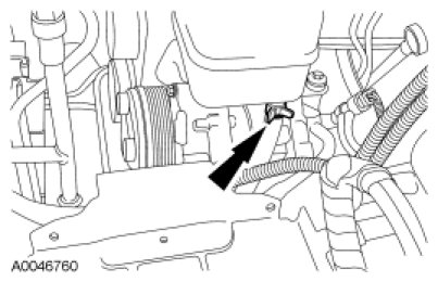
32. Connect the Power Steering Pressure (PSP) hose to the lower power steering pump fitting.
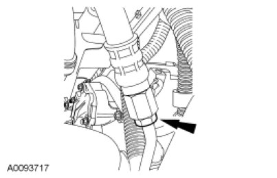
33. If equipped with A/C, position the A/C compressor manifold and install the bolt.
- Tighten to 20 Nm (177 lb-in).
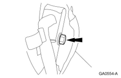
34. If equipped with A/C, connect the A/C high pressure switch electrical connector.
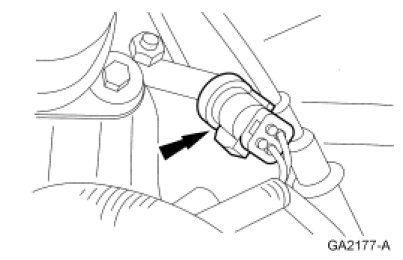
35. If equipped with A/C, connect the A/C field coil electrical connector.
36. Install the accessory drive belt.
37. NOTE: Do not fill the cooling system at this time.
Install the radiator.
38. Install the air cleaner housing cover.
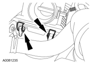
39. Connect the Mass Air Flow (MAF) sensor.
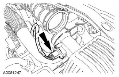
40. Install the fan blade.
41. NOTE: Align the hood with the hinge location marks made during removal.
Install the hood and the 4 bolts.
- Tighten to 12 Nm (106 lb-in).
42. Position the RH spark plug wires and attach the retainer to the RH valve cover stud. Coat the inside of the spark plug wire boots with silicone brake caliper grease and dielectric compound and connect the spark plug wires to the correct spark plugs.
43. Position the ignition coil, the bracket and the LH spark plug wires and attach the spark plug wire retainer to the LH vale cover stud. Coat the inside of the spark plug wire boots with silicone brake caliper grease and dielectric compound and connect the spark plug wires to the correct spark plugs.
44. Connect the fuel tube spring lock couplings.
45. NOTICE: If the engine is repaired or replaced because of upper engine failure, typically including valve or piston damage, check the intake manifold for metal debris. If metal debris is found, install a new intake manifold. Failure to follow these instructions can result in engine damage.
Install the intake manifold. For additional information, refer to Intake Manifold Service and Repair.
46. Connect the battery ground cable.
47. Fill the engine to the correct oil level with clean engine oil.
48. Fill the engine cooling system.
49. Fill the power steering system.
50. If equipped with A/C, recharge the A/C system.