Shift Interlock Solenoid: Service and Repair
Brake Shift Interlock Actuator
Removal and Installation
1. WARNING: Always deplete the backup power supply before repairing or installing any new front or side air bag supplemental restraint system (SRS) component and before servicing, removing, installing, adjusting or striking components near the front or side impact sensors or the restraints control module (RCM). Nearby components include doors, instrument panel, console, door latches, strikers, seats and hood latches.
Refer to the Description and Operation portion of Restraint Systems for location of the RCM and impact sensor(s).
To deplete the backup power supply energy, disconnect the battery ground cable and wait at least 1 minute. Be sure to disconnect auxiliary batteries and power supplies (if equipped).
Failure to follow these instructions may result in serious personal injury or death in the event of an accidental deployment.
Disconnect the battery ground cable. Wait at least one minute before proceeding with the procedure to allow the backup power supply to deplete its energy. For additional information, refer to Battery.
2. Remove the Supplemental Restraint System (SRS) steering column clockspring. For additional information, refer to Restraint Systems.
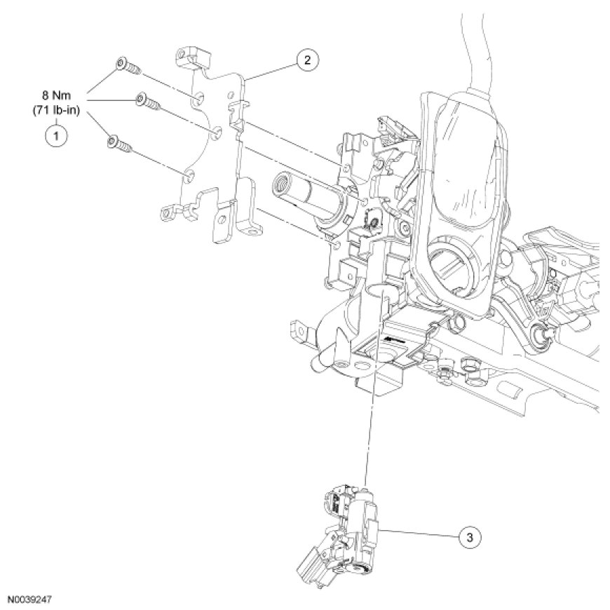
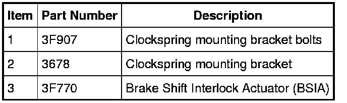
3. Remove the 3 clockspring mounting bracket bolts and remove the clockspring mounting bracket from the steering column.
- To install, tighten to 8 Nm (71 lb-in).
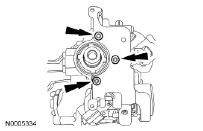
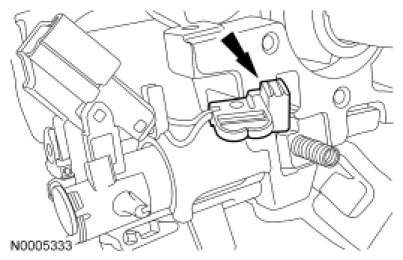
4. Release the clip retaining the Brake Shift Interlock Actuator (BSIA) and slide the BSIA down.
5. Remove the park position switch from the cavity and remove the BSIA assembly.
6. To install the BSIA, reverse the removal procedure.