Part 2
Engine
NOTICE: During engine repair procedures, cleanliness is extremely important. Any foreign material, including any material created while cleaning gasket surfaces that enters the oil passages, coolant passages or the oil pan, may cause engine failure.
NOTE: Assembly of the engine requires various inspections/measurements of the engine components (engine block, crankshaft, connecting rods, pistons and piston rings). These inspections/measurements will aid in determining if the engine components will require replacement.
All vehicles
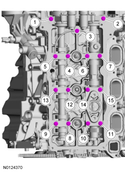
54. NOTE: Cylinder head camshaft bearing caps are numbered to verify that they are assembled in their original positions.
Install the 6 camshaft caps, mega cap, valve train oil tube and the 15 bolts in the sequence shown.
Tighten to 8 Nm (71 lb-in) then an additional 45 degrees.
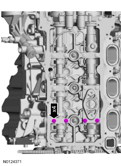
55. Loosen the 4 camshaft caps bolts.
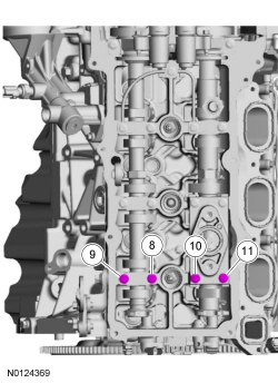
56. Tighten the 4 camshaft caps bolts in the sequence shown.
Tighten bolts 8, 9, 10 and 11 to 8 Nm (71 lb-in) then an additional 45 degrees.
57. NOTICE: If any components are installed new, the engine valve clearance must be checked/adjusted or engine damage may occur.
NOTE: Use a camshaft sprocket bolt to turn the camshafts.
Using a feeler gauge, confirm that the valve tappet clearances are within specification. If valve tappet clearances are not within specification, the clearance must be adjusted by installing new valve tappet(s) of the correct size. For additional information, refer to Valve Clearance Check.

58. Remove the 3 bolts and the LH valve train oil tube.

59. Rotate the LH camshafts to the TDC position as shown.

60. NOTE: The Camshaft Holding Tool will hold the camshafts in the TDC position.
Install the Camshaft Holding Tool onto the flats of the LH camshafts.

61. Using a new gasket, install the timing chain gear and the 9 bolts. Tighten in 2 stages in the sequence shown.
Stage 1: Tighten to 10 Nm (89 lb-in).
Stage 2: Tighten an additional 45 degrees.

62. Install the RH primary timing chain guide and the 2 bolts.
Tighten to 10 Nm (89 lb-in).

Engines with secondary timing chain tensioner removed
NOTICE: The following steps are only for the replacement of the secondary timing chain tensioners. Do not reuse the secondary timing chain tensioners if removed or damage to the engine may occur.
63. NOTE: Apply clean engine oil to the secondary timing chain tensioner O-ring seals and mega cap bore.
NOTE: Do not remove the secondary timing chain tensioner shipping clip, until instructed to do so.
Install the RH secondary timing chain tensioner by pushing it down all the way until a snap is heard and the tensioner is seated all the way down the mega cap bore.

64. Install the RH secondary timing chain tensioner shoe.

65. Remove and discard the RH secondary timing chain tensioner shipping clip.

66. Assemble the RH Variable Camshaft Timing (VCT) assembly, the RH exhaust camshaft sprocket and the RH secondary timing chain.
Align the colored links with the timing marks.

67. NOTE: It may be necessary to rotate the camshafts slightly, to install the RH secondary timing assembly.
Position the 2 RH VCT assemblies and secondary timing chain onto the camshafts by aligning the holes in the VCT assemblies with the dowel pins in the camshafts.

68. Install the 2 new RH VCT bolts and tighten in 4 stages.
Stage 1: Tighten to 40 Nm (30 lb-ft).
Stage 2: Loosen one full turn.
Stage 3: Tighten to 25 Nm (18 lb-ft).
Stage 4: Tighten an additional 180 degrees.

69. Activate the RH secondary timing chain tensioner by pressing down on the secondary tensioner shoe until it bottoms out, let go of the tensioner and it will spring up putting tension on the chain.

70. NOTICE: Do not use excessive force when installing the Variable Camshaft Timing (VCT) oil control solenoid. Damage to the mega cap could cause the cylinder head to be inoperable. If difficult to install the VCT oil control solenoid, inspect the bore and VCT oil control solenoid to ensure there are no burrs, sharp edges or contaminants present on the mating surface. Only clean the external surfaces as necessary.
NOTE: A slight twisting motion will aid in the installation of the VCT oil control solenoid.
NOTE: Keep the VCT oil control solenoid clean of dirt and debris.
Install the RH exhaust VCT oil control solenoid.
Tighten to 8 Nm (71 lb-in) then an additional 20 degrees.

71. NOTE: Apply clean engine oil to the secondary timing chain tensioner O-ring seals and mega cap bore.
NOTE: Do not remove the secondary timing chain tensioner shipping clip, until instructed to do so.
Install the LH secondary timing chain tensioner by pushing it down all the way until a snap is heard and the tensioner is seated all the way down the mega cap bore.

72. Install the LH secondary timing chain tensioner shoe.

73. Remove and discard the LH secondary timing chain tensioner shipping clip.

74. Assemble the 2 LH VCT assemblies and the LH secondary timing chain.
Align the colored links with the timing marks.

75. NOTE: It may be necessary to rotate the camshafts slightly, to install the LH secondary timing assembly.
Position the 2 LH VCT assemblies and secondary timing chain onto the camshafts by aligning the holes in the VCT assemblies with the dowel pins in the camshafts.

76. Install the 2 new LH VCT bolts and tighten in 4 stages.
Stage 1: Tighten to 40 Nm (30 lb-ft).
Stage 2: Loosen one full turn.
Stage 3: Tighten to 25 Nm (18 lb-ft).
Stage 4: Tighten an additional 180 degrees.

77. Activate the LH secondary timing chain tensioner by pressing down on the secondary tensioner shoe until it bottoms out, let go of the tensioner and it will spring up putting tension on the chain.

78. NOTICE: Do not use excessive force when installing the Variable Camshaft Timing (VCT) oil control solenoid. Damage to the mega cap could cause the cylinder head to be inoperable. If difficult to install the VCT oil control solenoid, inspect the bore and VCT oil control solenoid to ensure there are no burrs, sharp edges or contaminants present on the mating surface. Only clean the external surfaces as necessary.
NOTE: A slight twisting motion will aid in the installation of the VCT oil control solenoid.
NOTE: Keep the VCT oil control solenoid clean of dirt and debris.
Install the LH exhaust VCT oil control solenoid.
Tighten to 8 Nm (71 lb-in) then an additional 20 degrees.

Engines with secondary timing chain tensioner not removed
79. Compress the RH secondary chain tensioner and install the Secondary Chain Hold Down to retain the tensioner in the collapsed position.

80. Assemble the RH Variable Camshaft Timing (VCT) assembly, the RH exhaust camshaft sprocket and the RH secondary timing chain.
Align the colored links with the timing marks.
81. NOTE: It may be necessary to rotate the camshafts slightly, to install the RH secondary timing assembly.
Position the 2 RH VCT assemblies and secondary timing chain onto the camshafts by aligning the holes in the VCT assemblies with the dowel pins in the camshafts.
82. Install the 2 new RH VCT bolts and tighten in 4 stages.
Stage 1: Tighten to 40 Nm (30 lb-ft).
Stage 2: Loosen one full turn.
Stage 3: Tighten to 25 Nm (18 lb-ft).
Stage 4: Tighten an additional 180 degrees.
83. Compress the RH secondary timing chain tensioner and remove the Secondary Chain Hold Down.
Make sure the secondary timing chain is centered on the timing chain tensioner guides.
84. Compress the LH secondary chain tensioner and install the Secondary Chain Hold Down to retain the tensioner in the collapsed position.

85. Assemble the 2 LH VCT assemblies and the LH secondary timing chain.
Align the colored links with the timing marks.
86. NOTE: It may be necessary to rotate the camshafts slightly, to install the LH secondary timing assembly.
Position the 2 LH VCT assemblies and secondary timing chain onto the camshafts by aligning the holes in the VCT assemblies with the dowel pins in the camshafts.
87. Install the 2 new LH VCT bolts and tighten in 4 stages.
Stage 1: Tighten to 40 Nm (30 lb-ft).
Stage 2: Loosen one full turn.
Stage 3: Tighten to 25 Nm (18 lb-ft).
Stage 4: Tighten an additional 180 degrees.
88. Compress the LH secondary timing chain tensioner and remove the Secondary Chain Hold Down.
Make sure the secondary timing chain is centered on the timing chain tensioner guides.
All engines
89. Install the upper LH primary timing chain guide and the bolt.
Tighten to 10 Nm (89 lb-in).

90. Rotate the crankshaft 60 degrees to the Top Dead Center (TDC) position (crankshaft dowel at 11 o'clock).

91. Install the crankshaft timing chain sprocket with timing dot mark out.

92. NOTE: It may be necessary to rotate the camshafts slightly, to align the timing marks.
Install the primary timing chain with the colored links aligned with the timing marks on the VCT assemblies and the crankshaft sprocket.

93.Install the lower LH primary timing chain guide and the 2 bolts.
Tighten to 10 Nm (89 lb-in).

94. Install the primary timing chain tensioner arm.

95. Reset the primary timing chain tensioner.
Release the ratchet detent.
Using a soft-jawed vise, compress the ratchet plunger.
Align the hole in the ratchet plunger with the hole in the tensioner housing.
Install a suitable lockpin.
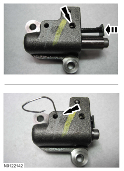
96. NOTE: It may be necessary to rotate the camshafts slightly to remove slack from the timing chain to install the tensioner.
Install the primary timing chain tensioner and the 2 bolts.
Tighten to 10 Nm (89 lb-in).
Remove the lockpin.
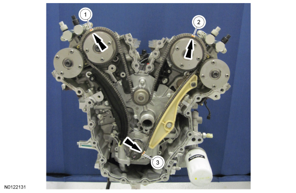
97. As a post-check, verify correct alignment of all timing marks.
There is 48 links in between the RH intake VCT assembly colored link (1) and the LH intake VCT assembly colored link (2).
There is 35 links in between RH intake VCT assembly colored link (2) and the 2 crankshaft sprocket links (3).
98. NOTICE: Do not use excessive force when installing the Variable Camshaft Timing (VCT) oil control solenoid. Damage to the mega cap could cause the cylinder head to be inoperable. If difficult to install the VCT oil control solenoid, inspect the bore and VCT oil control solenoid to ensure there are no burrs, sharp edges or contaminants present on the mating surface. Only clean the external surfaces as necessary.
NOTE: A slight twisting motion will aid in the installation of the VCT oil control solenoid.
NOTE: Keep the VCT oil control solenoid clean of dirt and debris.
Install the LH intake VCT oil control solenoid and the bolt.
Tighten to 8 Nm (71 lb-in) then an additional 20 degrees.

99. NOTICE: Do not use excessive force when installing the Variable Camshaft Timing (VCT) oil control solenoid. Damage to the mega cap could cause the cylinder head to be inoperable. If difficult to install the VCT oil control solenoid, inspect the bore and VCT oil control solenoid to ensure there are no burrs, sharp edges or contaminants present on the mating surface. Only clean the external surfaces as necessary.
NOTE: A slight twisting motion will aid in the installation of the VCT oil control solenoid.
NOTE: Keep the VCT oil control solenoid clean of dirt and debris.
Install the RH intake VCT oil control solenoid and the bolt.
Tighten to 8 Nm (71 lb-in) then an additional 20 degrees.

100. Remove the RH Camshaft Holding Tool.

101. Install the RH valve train oil tube and the 3 bolts and tighten in 2 stages.
Stage 1: Tighten to 8 Nm (71 lb-in).
Stage 2: Tighten an additional 45 degrees.

102. Remove the LH Camshaft Holding Tool.

103. Install the LH valve train oil tube and the 3 bolts and tighten in 2 stages.
Stage 1: Tighten to 8 Nm (71 lb-in).
Stage 2: Tighten an additional 45 degrees.
104. NOTE: Use Spindle Bearing Installer 205-149 to install the seal.
Using the Spindle Bearing Installer, install the front cover radial seal from the rear side of the front cover.

105. NOTICE: Failure to use Motorcraft(R) High Performance Engine RTV Silicone may cause the engine oil to foam excessively and result in serious engine damage.
NOTICE: Do not expose the Motorcraft(R) High Performance Engine RTV Silicone to engine oil for at least 90 minutes after installing the engine front cover. Failure to follow this procedure can cause engine oil leakage.
NOTE: The engine front cover and bolts 1, 2, 7, 8, 15, 17, 18, 19, 20 and 21 must be installed within 10 minutes of the initial sealant application. The remainder of the engine front cover bolts and the engine mount bracket bolts must be installed and tightened within 35 minutes of the initial sealant application. If the time limits are exceeded, the sealant must be removed, the sealing area cleaned and sealant reapplied. To clean the sealing area, use silicone gasket remover and metal surface prep. Failure to follow this procedure can cause future oil leakage.
Apply a 3.0 mm (0.11 in) bead of Motorcraft(R) High Performance Engine RTV Silicone on the inside edge of the engine front cover to the engine front cover sealing surfaces including the 2 engine front cover bolt bosses.
Apply a 5.5 mm (0.21 in) bead of Motorcraft(R) High Performance Engine RTV Silicone to the oil pan-to-cylinder block joint and the cylinder head-to-cylinder block joint areas of the engine front cover in 5 places as indicated.

106. NOTE: Make sure the 2 locating dowel pins are seated correctly in the cylinder block.
Install the engine front cover and bolts 1, 2, 7, 8, 15, 17, 18, 19, 20 and 21 and tighten in the sequence shown in 3 stages:
Stage 1: Tighten bolts 1, 2, 7, 8, 15, 17, 18, 19, 20 and 21 in sequence to 10 Nm (89 lb-in).
Stage 2: Tighten bolts 1, 2, 7, 8, 15, 17, 18, 19 and 20 in sequence to 20 Nm (177 lb-in) then an additional 45 degrees.
Stage 3: Tighten bolt 21 to 20 Nm (177 lb-in) then an additional 90 degrees.

107. Install the remaining 12 engine front cover bolts 3, 4, 5, 6, 9, 10, 11, 12, 13, 14, 16, 22 and tighten in the sequence shown in 3 stages:
Stage 1: Tighten bolts 3, 4, 5, 6, 9, 10, 11, 12, 13, 14, and 16 to 10 Nm (89 lb-in).
Stage 2: Tighten bolts 3, 4, 5, 6, 9, 10, 11, 12, 13, 14, and 16 to 20 Nm (177 lb-in) then an additional 45 degrees.
Stage 3: Tighten bolt 22 to 10 Nm (89 lb-in) then an additional 45 degrees.

108. Using a new gasket, install the oil filter adapter and the 5 bolts and tighten in sequence shown.
Tighten to 10 Nm (89 lb-in) and then an additional 45 degrees.
