Pinpoint Test B: The Courtesy Lamp(s) Are Inoperative
Interior Lighting
Pinpoint Test B: The Courtesy Lamp(s) Are Inoperative
Refer to Wiring Diagrams Set 89, Interior Lamps for schematic and connector information. Electrical Diagrams
Normal Operation
The Generic Electronic Module (GEM) supplies voltage to the interior lamps through the battery saver output circuit. To control the illumination of the courtesy lamps, the GEM (Generic Electronic Module) grounds the control side of the courtesy lamp relay located in the Central Junction Box (CJB). When the relay is energized, ground is supplied to the interior lamps.
The GEM (Generic Electronic Module) monitors the door ajar switch status. When the doors are closed, the door ajar switches are open, removing ground to the GEM (Generic Electronic Module). When the GEM (Generic Electronic Module) determines a door is open, the GEM (Generic Electronic Module) then energizes the courtesy lamp relay to illuminate the interior lamps.
- DTC B1315 (Battery Saver Relay Coil Circuit Short To Battery)- a continuous DTC that sets when the GEM (Generic Electronic Module) detects an open from the battery saver output circuit.
- DTC B1316 (Battery Saver Relay Coil Circuit Short To Ground)- a continuous DTC that sets when the GEM (Generic Electronic Module) detects a short to ground from the battery saver output circuit.
- DTC B2555 (Dome Lamp Output Circuit Short to Battery)- a continuous DTC that sets when the GEM (Generic Electronic Module) detects a short to battery from the courtesy lamp relay control circuit.
This pinpoint test is intended to diagnose the following:
- Fuse
- Wiring, terminals or connectors
- Courtesy lamp relay
- Front interior lamp
- GEM (Generic Electronic Module)
PINPOINT TEST B : THE COURTESY LAMP(S) ARE INOPERATIVE
NOTICE: Use the correct probe adapter(s) when making measurements. Failure to use the correct probe adapter(s) may damage the connector.
B1 CHECK THE OPERATION OF THE HORN
- Check the operation of the horn by pressing on the horn pad.
Does the horn sound?
Yes
GO to B2.
No
REFER to Horn.
B2 CHECK THE INTERIOR LAMP OPERATION
- Open the doors.
- Check the operation of the interior lamp(s) in both the ON and DOOR positions.
Are the interior lamp(s) inoperative in both positions?
Yes
If all the interior lamps are inoperative, GO to B3.
If an individual interior lamp is inoperative, GO to B5.
If both rear lamps are inoperative, INSTALL a new front interior lamp. REFER to Interior Lamp . TEST the system for normal operation.
No
If the lamps are inoperative in the ON position, GO to Pinpoint Test D. Pinpoint Test D: The Demand Lighting Is Inoperative
If the lamps are inoperative in the DOOR position, GO to B7.
B3 CHECK FOR VOLTAGE TO THE FRONT INTERIOR LAMP
- Disconnect: Front Interior Lamp C931A.
- Ignition ON.
- Measure the voltage between the front interior lamp C931A-1, circuit 29-LC7 (OG/BU), harness side and ground.
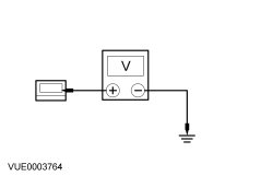
Is the voltage greater than 10 volts?
Yes
INSTALL a new front interior lamp. REFER to Interior Lamp . TEST the system for normal operation.
No
GO to B4.
B4 BYPASS THE GEM (Generic Electronic Module)
NOTE: If the fuse in the jumper wire fails, refer to the Wiring Diagrams to identify the possible causes of the circuit short. Electrical Diagrams
- Ignition OFF.
- Disconnect: GEM (Generic Electronic Module) C201D.
- Connect: Front Interior Lamp C931A.
- Place the front interior lamp control switch in the ON position.
- Connect a fused jumper wire between the GEM (Generic Electronic Module) C201D-2, circuit 29-AA17 (OG/WH), harness side and the GEM (Generic Electronic Module) C201D-6, circuit 29-LC7 (OG/BU), harness side.
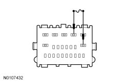
Do the interior lamps illuminate?
Yes
REMOVE the jumper wire. GO to B13.
No
REMOVE the jumper wire. REPAIR circuit 29-LC7 (OG/BU) for an open. TEST the system for normal operation.
B5 CHECK FOR VOLTAGE TO THE INTERIOR LAMP
- Disconnect: Inoperative Interior Lamp.
- Ignition ON.
- Measure the voltage between the inoperative lamp, harness side and ground as follows:
Inoperative Lamp Connector-Pin Circuit Front C931A-1 29-LC7 (OG/BU) Center C901A-1 29-LB25 (OG/BU) Rear C932A-1 29-LB25 (OG/BU)
Is the voltage greater than 10 volts?
Yes
For the front interior lamp, INSTALL a new front interior lamp. REFER to Interior Lamp . TEST the system for normal operation.
For the rear interior lamps, GO to B6.
No
REPAIR the circuit in question for an open. TEST the system for normal operation.
B6 CHECK THE REAR INTERIOR LAMP GROUND CIRCUIT FOR AN OPEN
- Measure the voltage between the inoperative rear interior lamp, harness side as follows:
Inoperative Lamp Connector-Pin/ Circuit Connector-Pin/ Circuit Center C901A-1 29-LB25 (OG/BU) C901B-1 31S-LB25 (BK/BU) Rear C932A-1 29-LB25 (OG/BU) C932B-1 31S-LB25 (BK/BU)
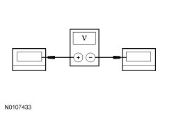
Is the voltage greater than 10 volts?
Yes
INSTALL a rear interior lamp for the lamp in question. TEST the system for normal operation.
No
REPAIR circuit 31S-LB25 (BK/BU) for an open. TEST the system for normal operation.
B7 CHECK THE INTERIOR LAMP RELAY
- Disconnect: Courtesy Lamp Relay.
- Substitute a known good relay and retest the system.
Do the courtesy lamps operate correctly?
Yes
REMOVE the known good relay. INSTALL a new courtesy lamp relay. TEST the system for normal operation.
No
REMOVE the known good relay. GO to B8.
B8 CHECK FOR VOLTAGE TO THE COURTESY LAMP RELAY COIL
- Measure the voltage between the courtesy lamp relay pin 1, circuit 29-LC8 (OG), CJB (Central Junction Box) face side, and ground.

Is the voltage greater than 10 volts?
Yes
GO to B9.
No
VERIFY the CJB (Central Junction Box) fuse 153 (7.5A) is OK. If OK, REPAIR circuit 29-LC8 (OG) for an open. TEST the system for normal operation. If not OK, REFER to the Wiring Diagrams to identify the possible causes of the circuit short. Electrical Diagrams
B9 CHECK THE COURTESY LAMP RELAY GROUND CIRCUIT
- Measure the voltage between the courtesy lamp relay pin 1, circuit 29-LC8 (OG), CJB (Central Junction Box) face side, and the courtesy lamp relay pin 3, circuit 31-DA1 (BK), CJB (Central Junction Box) face side.
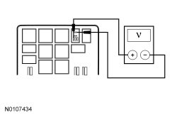
Is the voltage greater than 10 volts?
Yes
GO to B10.
No
REPAIR circuit 31-DA1 (BK) for an open. TEST the system for normal operation.
B10 BYPASS THE COURTESY LAMP RELAY
- Ignition ON.
- Place the front interior lamp control switch in the DOOR position.
- Connect a fused jumper wire between the courtesy lamp relay pin 3, circuit 31-DA1 (BK), CJB (Central Junction Box) face side, and the courtesy lamp relay pin 5, circuit 31S-LC7 (BK/BU), CJB (Central Junction Box) face side.
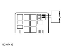
Do the interior lamps illuminate?
Yes
REMOVE the jumper wire. GO to B12.
No
LEAVE the jumper wire connected. GO to B11.
B11 CHECK FOR VOLTAGE TO THE FRONT INTERIOR LAMP USING THE CONNECTOR GROUND
- Disconnect: Front Interior Lamp C931A and C931B.
- Measure the voltage between the front interior lamp C931A-1, circuit 29-LC7 (OG/BU), harness side and the front interior lamp C931B-1, circuit 31S-LC7 (BK/BU), harness side.
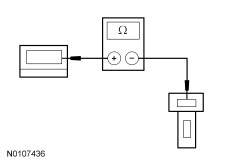
Is the voltage greater than 10 volts?
Yes
REMOVE the jumper wire. INSTALL a new front interior lamp. REFER to Interior Lamp . TEST the system for normal operation.
No
REMOVE the jumper wire. REPAIR circuit 31S-LC7 (BK/BU) for an open. TEST the system for normal operation.
B12 CHECK THE COURTESY LAMP RELAY CONTROL CIRCUIT
NOTE: If the fuse in the jumper wire fails, repair circuit 31S-LC18 (BK/BU) for a short to voltage.
- Ignition OFF.
- Connect: Courtesy Lamp Relay.
- Disconnect: GEM (Generic Electronic Module) C201E.
- Ignition ON.
- Connect a fused jumper wire between the GEM (Generic Electronic Module) C201E-21, circuit 31S-LC18 (BK/BU), harness side, and ground.
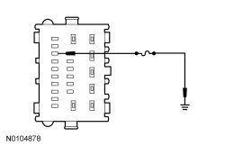
Do the interior lamps illuminate?
Yes
REMOVE the jumper wire. GO to B13.
No
REMOVE the jumper wire. REPAIR circuit 31S-LC18 (BK/BU) for an open. TEST the system for normal operation.
B13 CHECK FOR CORRECT GEM (Generic Electronic Module) OPERATION
- Disconnect all the GEM (Generic Electronic Module) connectors.
- Check for:
- corrosion
- pushed-out pins
- Connect all the GEM (Generic Electronic Module) connectors and make sure they seat correctly.
- Operate the system and determine if the concern is still present.
Is the concern still present?
Yes
INSTALL a new GEM (Generic Electronic Module). TEST the system for normal operation.
No
The system is operating correctly at this time. The concern may have been caused by a loose or corroded connector.