Electronic Column Lock Module - Assemble
Electronic Column Lock Module - Assemble - Off Vehicle (Column Shift)^ Tools Required
- J 42759 Ignition Switch Connector Release Tool
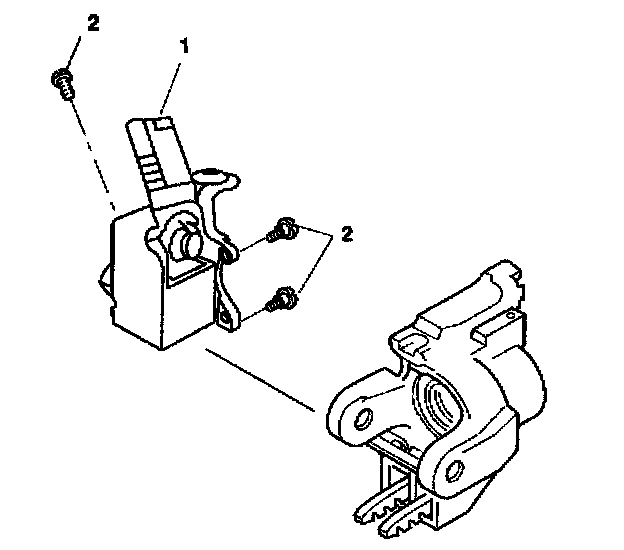
1. Align the electronic lock module assembly (1) with the steering column tilt head assembly.
Notice: Refer to Fastener Notice in Service Precautions.
2. Screw the 3 TORX(R) screws (2) into the electronic lock module assembly (1).
Tighten the 3 TORX(R) screws to 7 Nm (62 inch lbs.).
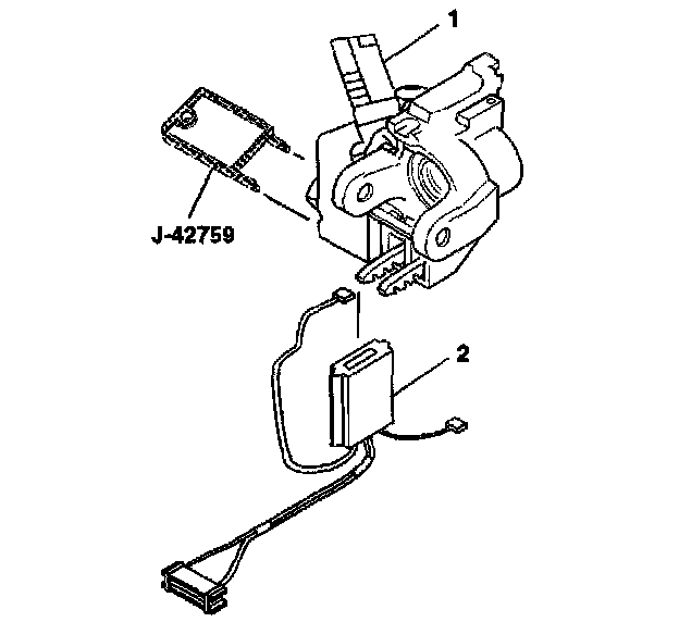
3. Insert J 42759 into the electronic lock module assembly (1) and slide the ignition and key alarm switch assembly (2) in.
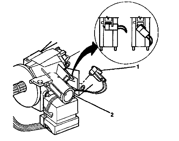
4. Push the key alarm connector (1) into the electronic lock module assembly (2).
5. Rotate the key alarm connector (1) 90 degrees so that the key alarm connector (1) locks into place.
6. Install the passkey connector into the electronic lock module assembly (2).
7. Place steering column lock cylinder set into the OFF position.
8. Place the shift lever clevis into the PARK position.
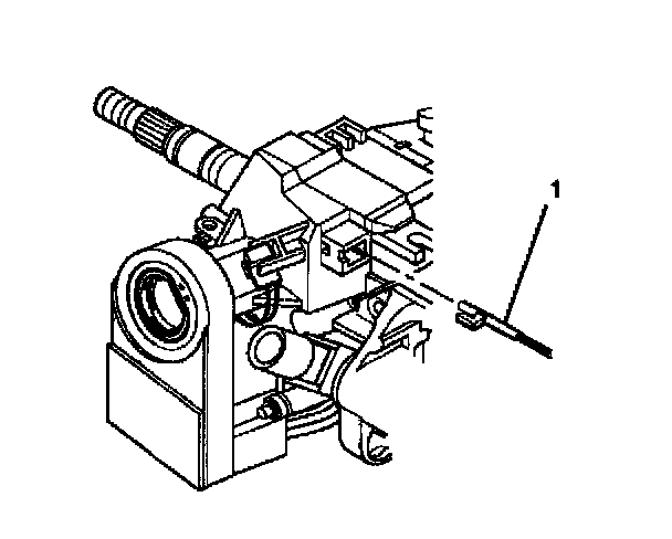
9. Press the locking tab on the end of the park lock cable assembly (1) into the slot in the electronic lock module assembly.
Important: The abrasion sleeve must be installed back onto the steering column wire harness assembly. The electronic lock module assembly wires and connector must be hanging out of the middle of the abrasion sleeve.
10. Install the upper tilt head components.
11. Enable the inflatable restraint steering wheel module.