Transmission End Cover

End Cover and Idler Gears Removal
Special Tools Required
Mainshaft holder 07GAB-PF50101 or 07GAB-PF50100
NOTE: Refer to the Exploded View as needed during the following procedure.
1. Remove the transmission range switch cover.
2. Remove the harness clamp bolt and the 2 transmission range switch bolts, then remove the transmission range switch.
3. Remove the 16 bolts securing the end cover, then remove the end cover.
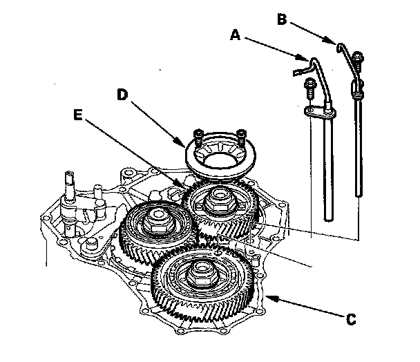
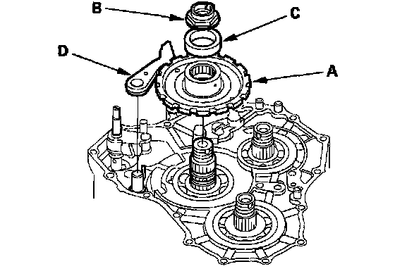
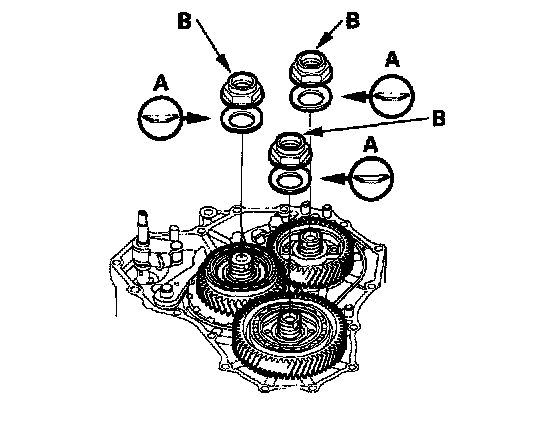
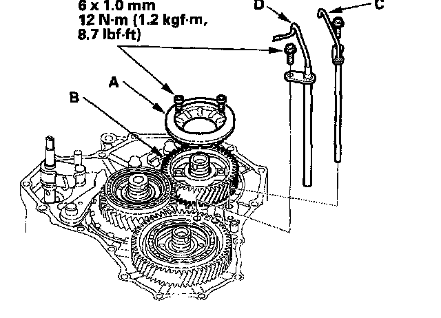
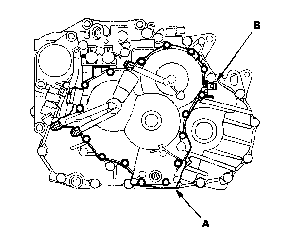
4. Remove the pivot pipe (A) and the lubrication pivot pipe (B) from the transmission housing (C), then remove the pivot flange (D) from the mainshaft idler gear (E).
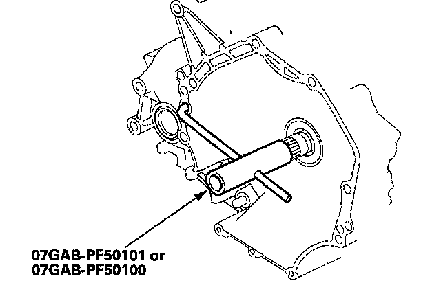
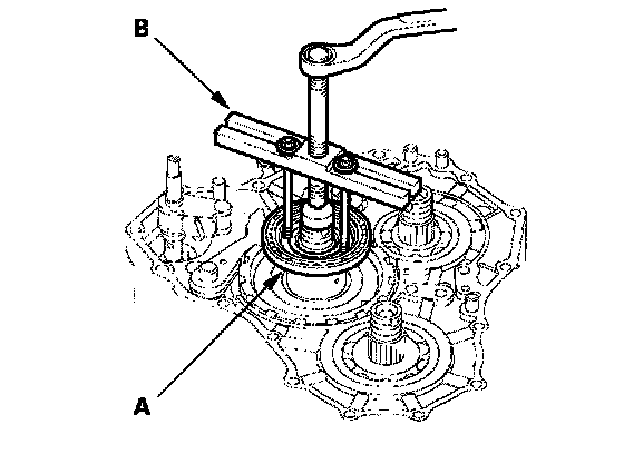
5. Slip the special tool onto the mainshaft.
6. Engage the park pawl with the park gear.
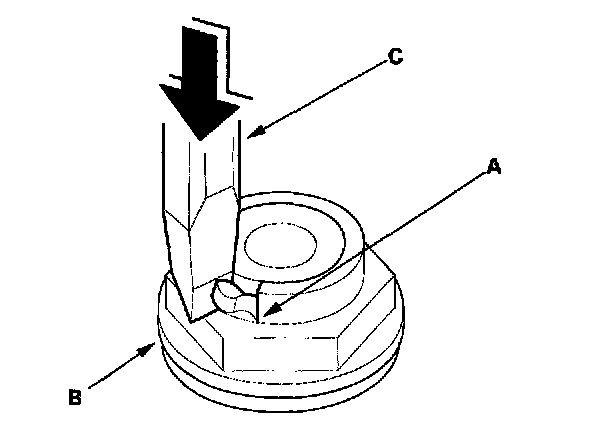
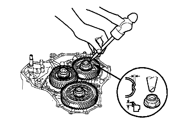
7. Cut the lock tabs (A) of each shaft locknut (B) using a chisel (C). Then remove the locknuts and conical spring washers from each shaft.
NOTE:
- Countershaft and secondary shaft locknuts have left-hand threads.
- Clean the old locknuts; they are used to install the press fit idler gears on the mainshaft and secondary shaft, and the park gear and bearing hub on the countershaft.
- Keep all of the chiseled particles out of the transmission.
8. Remove the special tool from the mainshaft.
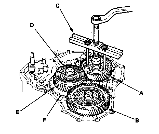
9. Remove the mainshaft idler gear (A) and the secondary shaft idler gear (B) with a puller (C).
10. Remove the bearing hub (D) with the puller from the countershaft, then remove the countershaft idler gear (E) and bearings.
11. Remove the park gear (F) with the puller.
12. Remove the park pawl, spring, shaft, and shaft stop.
13. Remove the park lever from the control shaft.
14. Remove the line bolts, then remove the ATF cooler lines.
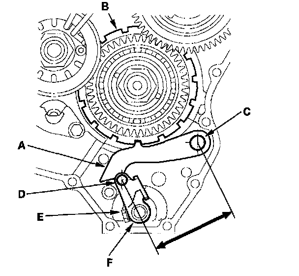
Park Lever Stop Inspection and Adjustment
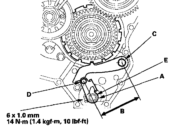
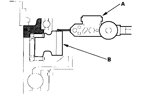
1. Set the park lever (A) in the P position.
2. Measure the distance (B) between the park pawl shaft (C) and the park lever roller pin (D).
STANDARD: 84.6 - 85.6 mm (3.33 - 3.37 inch)

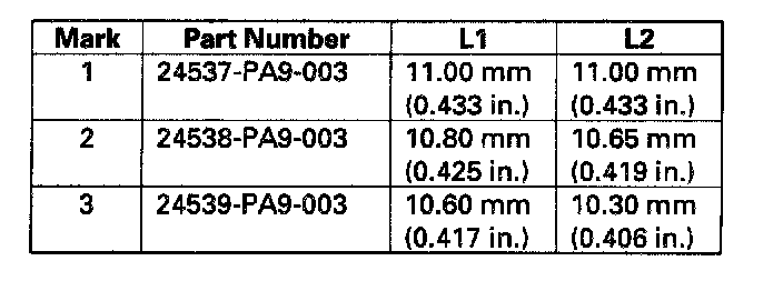
3. If the measurement is out of tolerance, select and install the appropriate park lever stop (E) from the table.
4. After replacing the park lever stop, make sure the distance is within tolerance.
End Cover and Idler Gears Installation
Special Tools Required
Mainshaft holder 07GAB-PF50101 or 07GAB-PF50100

1. Install the park lever (A) and park lever stop (B) on the control shaft (C), then install the lock bolt (D) with a new lock washer (E). Do not bend the lock tab of the lock washer until step 25.
2. Lubricate the following parts with ATF:
- Splines of the countershaft, the park gear, and the old locknut.
- Threads of the countershaft and the old locknut.
- Old conical spring washer.
3. Install the park gear (A) using the old locknut (B) and a collar (C). Hold the park pawl (D) against the park gear, then tighten the old locknut until the shaft splines come out slightly over the park gear splines.
NOTE:
- Do not use an impact wrench.
- Countershaft locknut has left-hand threads.
4. Remove the locknut and the collar, then install only the bearing hub/bearing assembly (A) and old conical spring washer (B). Tighten the old locknut (C) to 226 Nm (23.0 kgf-m, 166 ft. lbs.), then remove the locknut and conical spring washer.
NOTE: Use a torque wrench to tighten the locknut. Do not use an impact wrench.
5. Remove the bearing hub/bearing assembly (A) with a puller (B).
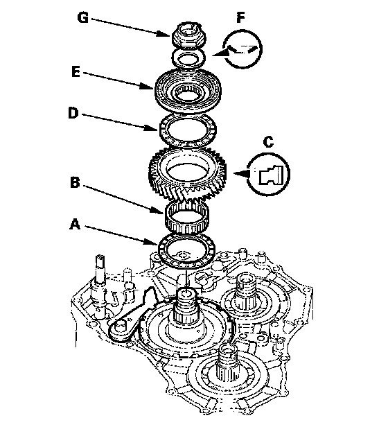
6. Install the thrust needle bearing (A), needle bearing (B), countershaft idler gear (C), thrust needle bearing (D), bearing hub/bearing assembly (E), and the old conical spring washer (F). Then tighten the old locknut (G) to 164 Nm (17.0 kgf-cm, 123 ft. lbs.).
NOTE: Use a torque wrench to tighten the locknut. Do not use an impact wrench.
7. Set the dial indicator (A) to the countershaft idler gear (B) as shown.
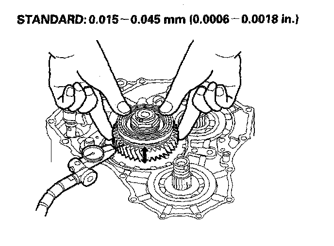
8. Measure the countershaft idler gear axial clearance in at least three places, while moving the countershaft idler gear. Use the average as the actual clearance.
9. If the clearance is out of standard, remove the bearing hub/bearing assembly using a puller as described on the previous page.

10. Select and install the new bearing hub/bearing assembly, then recheck.
11. After replacing the bearing hub/bearing assembly, make sure the clearance is within standard.
12. Remove the old locknut and old conical spring washer from the countershaft.
13. Install the special tool onto the mainshaft.
14. Lubricate the following parts with ATF:
- Splines of the mainshaft, secondary shaft, and idler gears.
- Threads of the mainshaft and secondary shaft. Threads of the old mainshaft and secondary shaft locknuts.
- Old conical spring washers.

15. Install the mainshaft idler gear (A) and the old conical spring washer (B) on the mainshaft (C). Tighten the old locknut (D) to 226 Nm (23.0 kgf-cm, 166 ft. lbs.) to seat the mainshaft idler gear.
NOTE: Use a torque wrench to tighten the locknut. Do not use an impact wrench.
16. Install the secondary shaft idler gear (E) and the old conical spring washer (F) on the secondary shaft (G). Tighten the old locknut (H) to 226 Nm (23.0 kgf-cm, 166 ft. lbs.) to seat the secondary shaft idler gear.
NOTE: Use a torque wrench to tighten the locknut. Do not use an impact wrench. Secondary shaft locknut has left-hand threads.
17. Remove the old locknuts and old conical spring washers from the mainshaft and the secondary shaft.
18. Lubricate the threads of each shaft, the new locknuts, and the new conical spring washers with ATF.
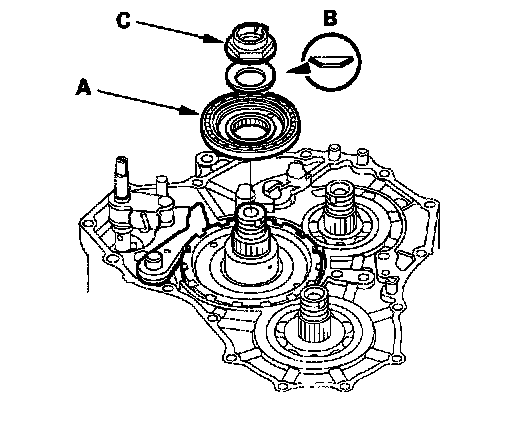
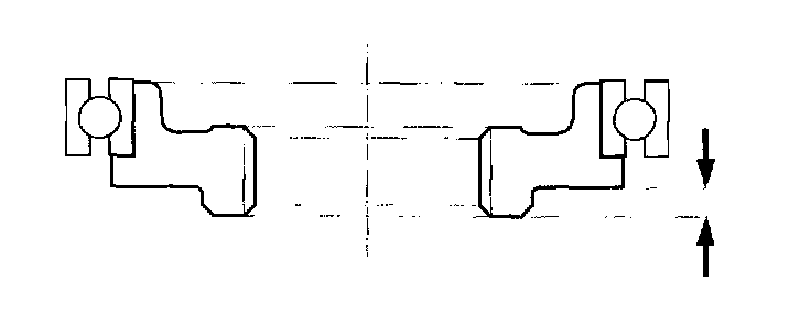
19. Install the new conical spring washers (A) in the direction shown, and install the new locknuts (B).
20. Tighten the locknut to 167 Nm, (17.0 kgf-cm, 123 ft. lbs.).
NOTE: Use a torque wrench to tighten the locknut. Do not use an impact wrench. Countershaft and secondary shaft locknuts have left-hand threads.
21. Stake each locknut into its shaft using a 3.5 mm punch.
22. Install the pivot flange (A) on the mainshaft idler gear (B), then install the lubrication pivot pipe (C) and the pivot pipe (D) on the transmission housing.
23. Set the park lever in P position, then verify that the park pawl (A) engages the park gear (B).
24. If the park pawl does not engage fully, check the distance between the pawl shaft (C) and the park lever roller pin (D).
25. Tighten the lock bolt (E), and bend the lock tab of the lock washer (F) against the lock bolt head.
26. Install the end cover (A) with the two dowel pins, new O-rings, new gasket, and harness clamp bracket (B). Tighten the 16 bolts to 12 Nm, (1.2 kgf-cm, 8.7 ft. lbs.).

27. Set the transmission range switch to N position.
NOTE: The transmission range switch clicks in N position.
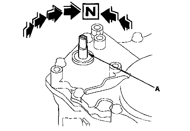
28. Set the control shaft (A) to the N position by turning it.
NOTE: Be careful not to squeeze the end of the control shaft tips together when turning into position. If the tips are squeezed together it will cause a faulty shift signal or position due to the play between the control shaft and position switch.
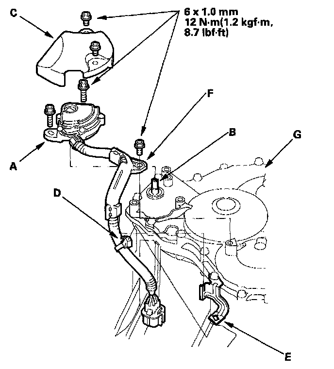
29. Install the transmission range switch (A) gently on the control shaft (B), then secure it with the bolts. Take care not to move the transmission range switch when tightening the bolts.
30. Install the transmission range switch cover (C); install the harness clamp (D) on the clamp bracket (E); install the harness clamp (F) on the end cover (G).
31. Install the ATF cooler lines and new sealing washers. Tighten the line fittings to 28 Nm (2.9 kgf-cm, 21 ft. lbs.)
32. Install the breather tube.
33. Install the ATF dipstick.