Accelerator Pedal Assembly/Sensor - Adjustment Update
00-045August 14, 2001
Applies To:
2000-02 Passport - ALL
Service Manual Update: Accelerator Pedal Position Sensor (APPS)
(Supersedes 00-045, dated May 23, 2000)
Updated information is shown by asterisks and black bars.
BACKGROUND
When the accelerator pedal position sensor (APPS) or the accelerator pedal assembly is replaced for any reason, you must adjust the APPS. *This procedure is missing in the 2000 service manual and is wrong in the 2001 and 2002 service manuals. Make a note on page 6E2-539 of the 2000 Passport Fuel and Emissions manual, on page 6E2-553 of the 2001 Passport Fuel and Emissions manual, and on page 6E2-545 of the 2002 Passport Fuel and Emissions manual to refer to this bulletin.*
ADJUSTMENT PROCEDURE
1. Replace the APPS or the accelerator pedal assembly, and leave the mounting screws for the APPS loose.
2. Connect the PGM Tester to the data link connector (DLC), and turn the ignition switch to ON (II).
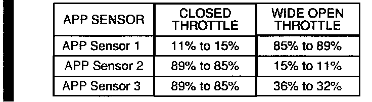
*3. While watching the APP Sensor values in the Engine Data List, adjust the APPS by turning it until the values are within the ranges shown at closed pushed all the way down), then tighten the throttle and wide open throttle (accelerator pedal mounting screws and recheck the values.
^ If all three sensors are within range, go to step 12.
^ If APP Sensor 1, APP Sensor 2, and/or APP Sensor 3 cannot be brought into range, go to step 4.
4. Troubleshoot for an open circuit or a PCM malfunction.
^ If APP Sensor 1 has a value of 0% or APP Sensor 2 and/or APP Sensor 3 have a value of 99%, an open circuit exists or the PCM is malfunctioning. Repair the circuit or replace the PCM, and repeat step 3.
^ If you don't find a problem, go to step 5.
5. Disconnect the 10P connector from the APPS.
6. View the APP Sensor values in the Engine Data List.
^ If APP Sensor 1 has a value of 0% or APP Sensor 2 and/or APP Sensor 3 have a value of 99%, go to step 7.
^ If APP Sensor 1 has a value other than 0%, or APP Sensor 2 and/or APP Sensor 3 have a value other than 99%, a short circuit exists or the PCM is malfunctioning. Repair the circuit or replace the PCM, and repeat step 3.
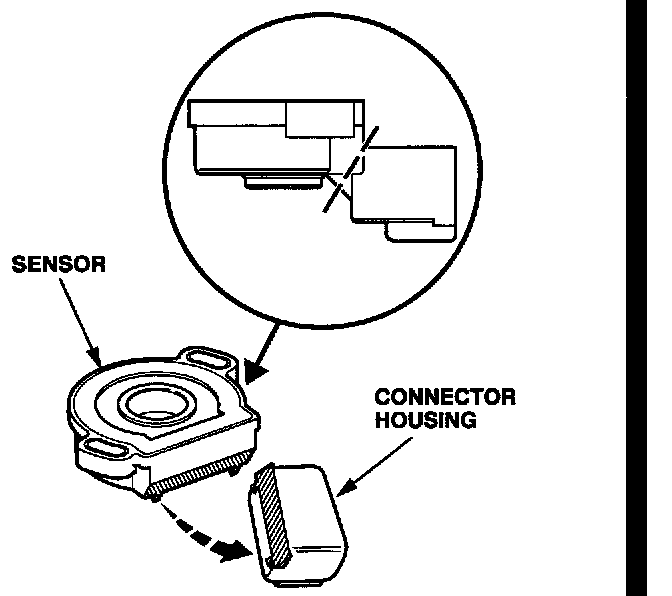
7. Modify the original APPS by cutting the connector housing off of the sensor.
8. Connect the 10P connector to the modified APPS connector housing.
9. Using a DVOM, check the voltage between the reference voltage pin for each sensor and ground.
^ If the sensor circuits all read 5.0 volts, go to step 11.
^ If any sensor circuit is above or below 5.0 volts, go to step 10.
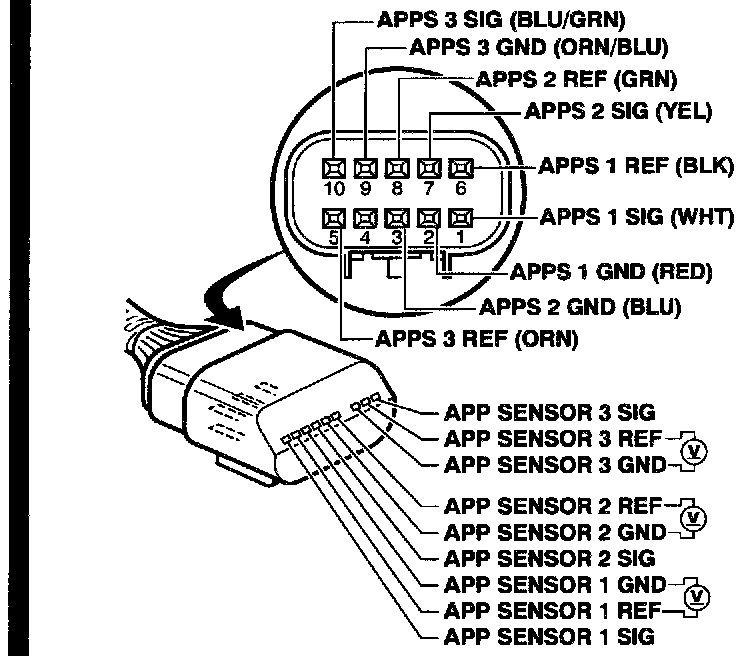
10. Troubleshoot for an internal short in another sensor or a PCM malfunction.
^ To find the sensor with an internal short, monitor the incorrect reference voltage, and disconnect each sensor (FTPS, EGR, MAP, TPS, CKP, and CMP) one at a time until the reference voltage reads 5.0 volts. Replace that sensor, and repeat step 3.
^ To find a malfunctioning PCM, replace it with a known-good PCM. If all three sensors (APP Sensor 1, APP Sensor 2, and APP Sensor 3) are within range, the original PCM is faulty; replace it and repeat step 3.
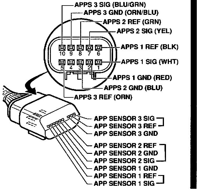
11. Using a jumper wire, connect the reference voltage of each circuit to its signal input and view the APP Sensor values in the Engine Data List. APP Sensor 1 should have a value of 99%, and APP Sensor 2 and APP Sensor 3 should each have a value of 0%.
^ If the values are not as specified, troubleshoot for high resistance on the signal input or a PCM malfunction. Repair the circuit or replace the PCM, then repeat step 3.
^ If the values are as specified, the problem may be intermittent. Disconnect the 10P connector from the modified APPS, and connect it to the new APPS; then repeat step 3. Wiggle the APPS wires as you go through the adjustment procedure to find the intermittent problem.
12. Turn off the ignition switch, and disconnect the PGM Tester.*

DISCLAIMER