Antilock Brakes / Traction Control Systems: Description and Operation
System DescriptionPart 1:

Part 2:


VSA Control Unit Inputs and Outputs for 47P Connector
ABS Features
When the brake pedal is pressed while driving, the wheels can lock before the vehicle comes to a stop. In such an event, the maneuverability of the vehicle is reduced if the front wheels are locked, and the stability of the vehicle is reduced if the rear wheels are locked, creating an extremely unstable condition. The ABS precisely controls the slip rate of the wheels to ensure maximum grip force from the tires, and it thereby ensures maneuverability and stability of the vehicle.
The ABS calculates the slip rate of the wheels based on the vehicle speed and the wheel speed, then it controls the brake fluid pressure to reach the target slip rate.
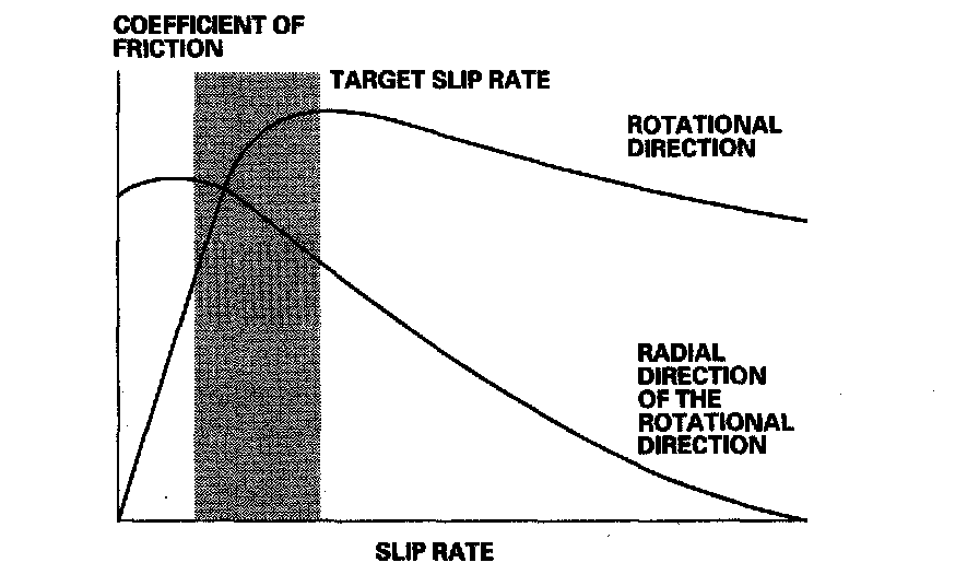
Grip Force of Tire and Road Surface
TCS Features
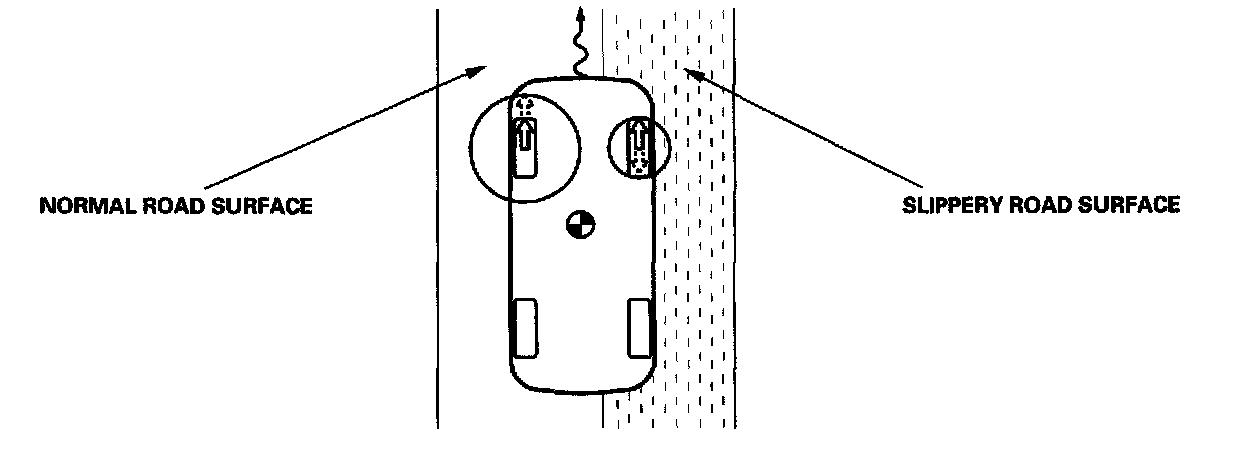
The TCS provides low-speed traction. When a drive wheel loses traction on a slippery road surface and starts to spin, the VSA modulator-control unit applies brake pressure to slow the spinning wheel. At that time, the VSA control unit sends a traction control signal to reduce engine power.
Brake Assist Function
If the brake operating force by driver is not enough in panic braking situations, it can not make the maximum braking force of the vehicles.
This function supports the driver in this case.
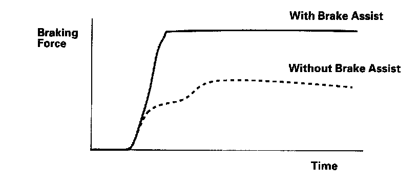
In this case, this function makes the bigger braking force than the brake operating force by driver.
Brake Assist Control Pattern
The VSA control unit calculates the master cylinder pressure gradient from the pressure sensor signal and the wheel speed for each wheel from the wheel speed sensor signal. If panic braking is detected by monitoring the master cylinder pressure gradient, increase all wheel cylinder pressure.
After the wheel cylinder pressure increased, if the VSA control unit judges slip condition from the wheel speed for each wheel and wheel acceleration, the VSA control unit decides one of the three pressure modification mode which are increase decrease and hold according to the wheel slip status, to regulate the wheel cylinder pressure.
VSA System Features
Oversteer control
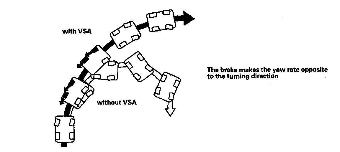
Applies the brake to the front and rear outside wheels
Understeer control (in acceleration)
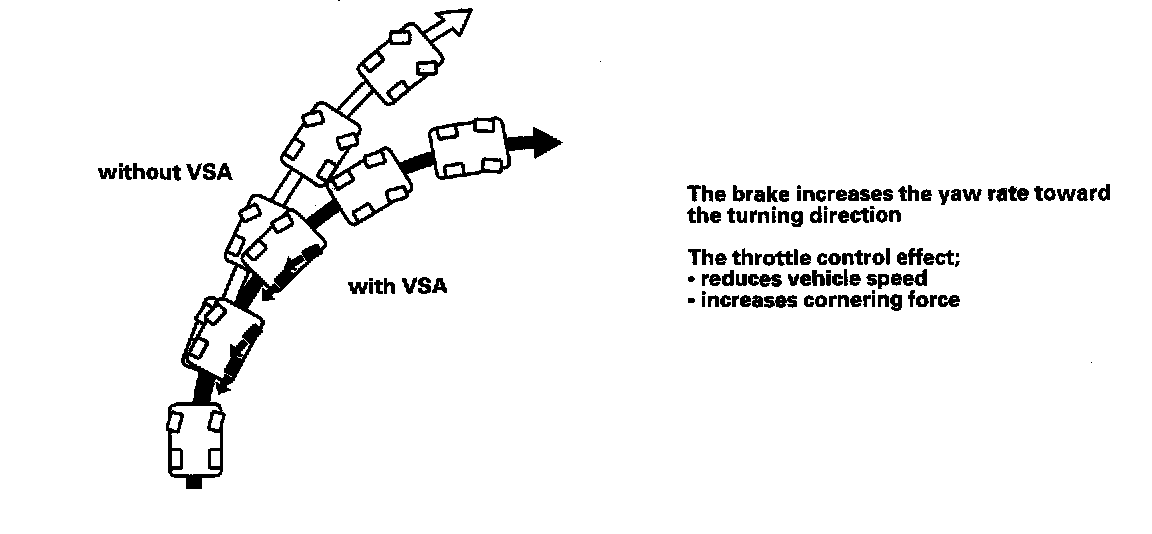
^ Applies the brake to the front and rear inside wheels
^ Controls the engine torque
Modulator Unit
The modulator unit consists of the inlet solenoid valve, outlet solenoid valve, VSA normally open (NO) solenoid valve, VSA normally closed (NC) solenoid valve, reservoir, pump, pump motor, and the damping chamber. The modulator controls the caliper fluid pressure directly. It is a circulating-type modulator because the brake fluid circulates through the caliper, the reservoir, and the master cylinder.
The hydraulic control has three modes: Pressure intensifying, pressure retaining, and pressure reducing. The hydraulic circuit is an independent four channel type, one channel for each wheel.
ABS Control
Pressure intensifying mode
VSA NO valve open, VSA NC valve closed, inlet valve open, outlet valve closed.
Master cylinder fluid is pumped out to the caliper.
Pump motor
When starting the pressure reducing mode, the pump motor is ON. When stopping ABS operation, the pump motor is OFF.
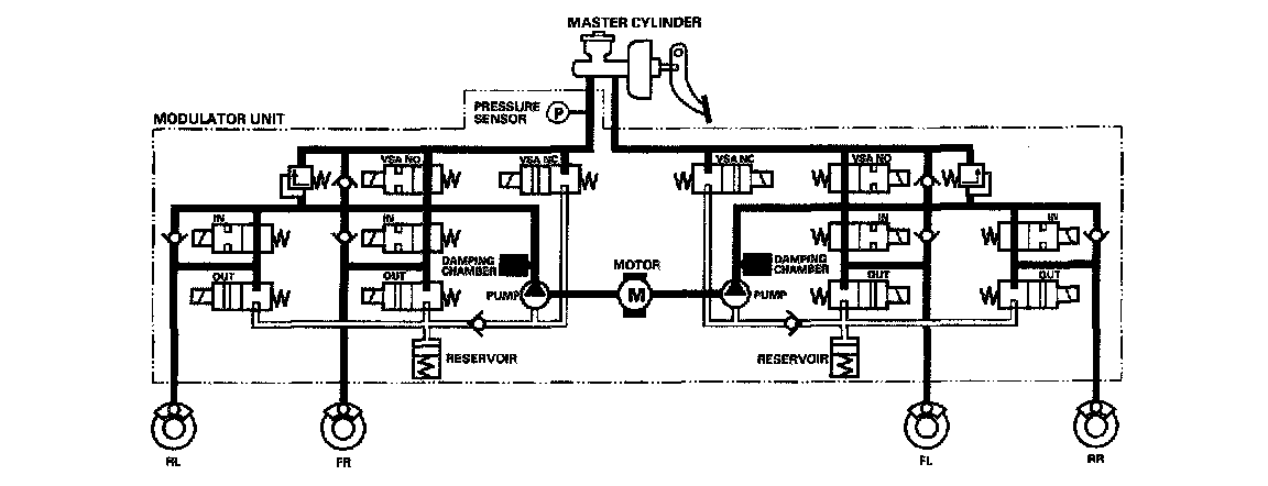
The reservoir fluid is pumped out by the pump, through the damping chamber, to the master cylinder.
Pressure retaining mode
VSA NO valve open, VSA NC valve closed, inlet valve closed, outlet valve closed.
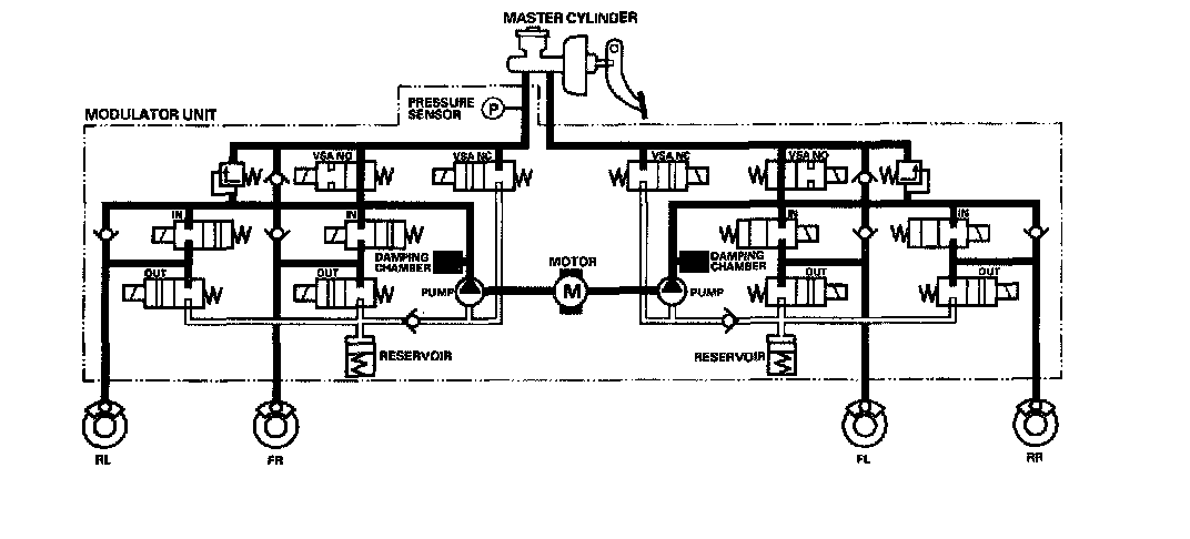
Caliper fluid is retained by the inlet valve and outlet valve.
Pressure reducing mode
VSA NO valve open, VSA NO valve closed, inlet valve closed, outlet valve open.
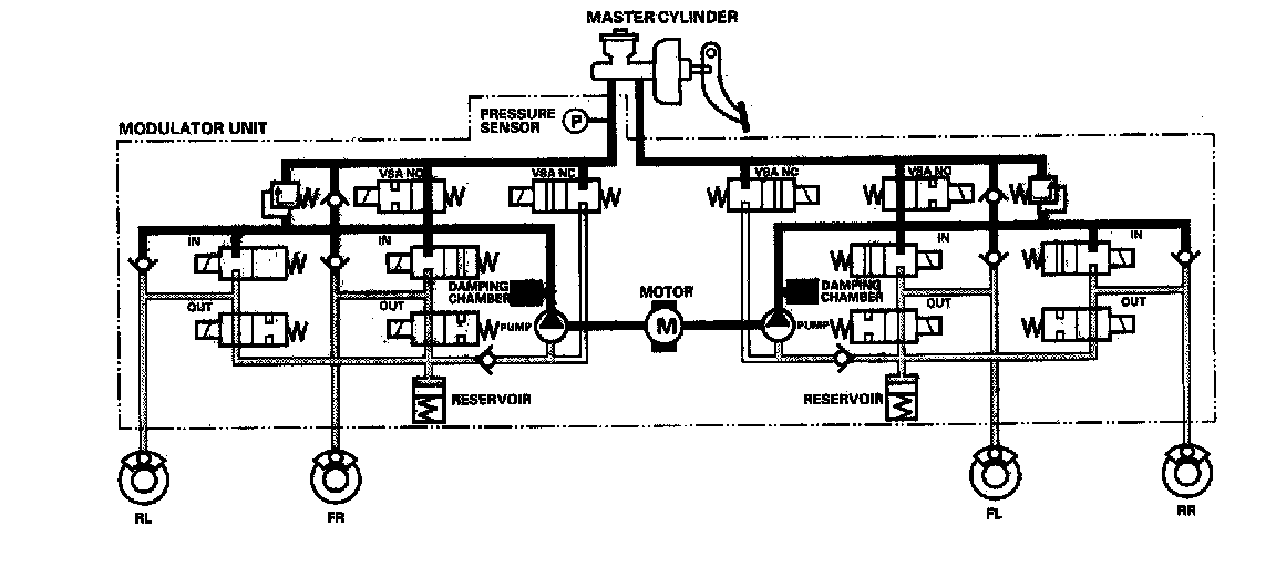
Caliper fluid flows through the outlet valve to the reservoir.
TCS Control
Pressure intensifying mode
VSA NO valve closed, VSA NC valve open, inlet valve open, outlet valve closed, pump motor ON.
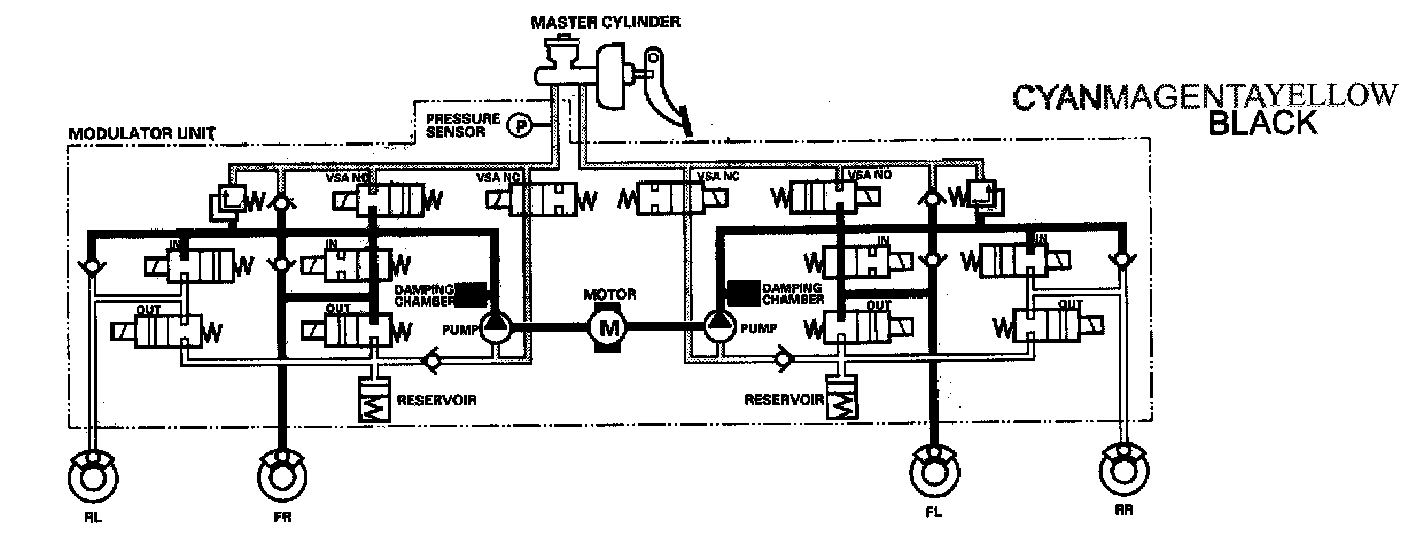
The reservoir and master cylinder fluid is pumped out by the pump, through the damping chamber, to the front caliper.
Pressure retaining mode
VSA NO valve closed, VSA NC valve open, inlet valve closed, outlet valve closed, pump motor ON.
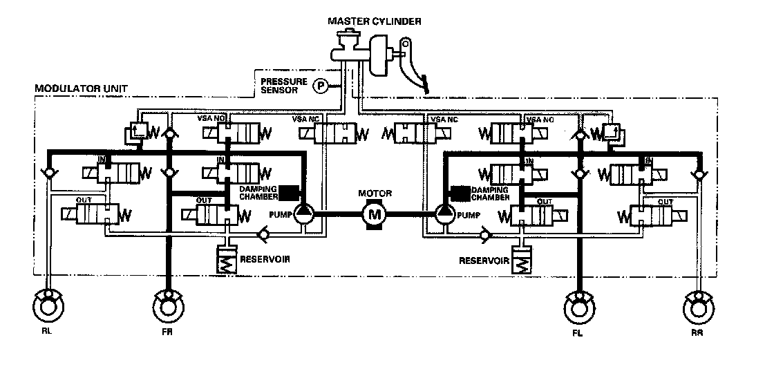
Front caliper fluid is retained by the inlet valve and outlet valve.
Pressure reducing mode
VSA NO valve closed, VSA NC valve open, inlet valve closed, outlet valve open, pump motor ON.
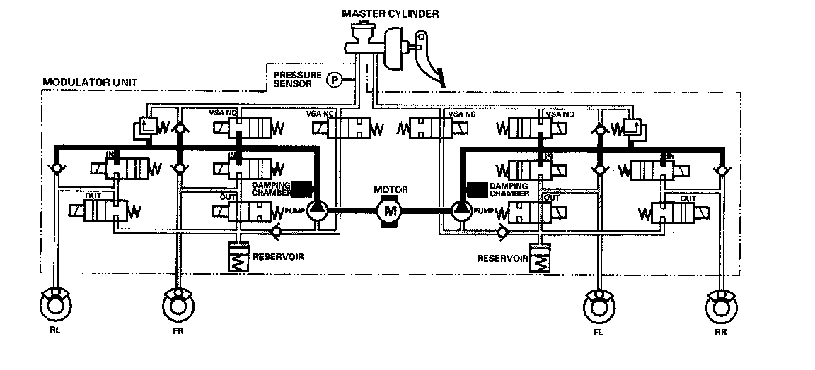
Caliper fluid flows through the outlet valve to the reservoir.
VSA Control
Pressure intensifying mode
VSA NO valve closed, VSA NC valve open, inlet valve open, outlet valve closed, pump motor ON.
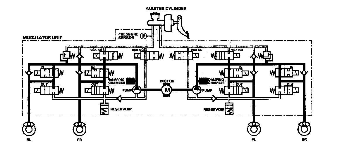
The reservoir and master cylinder fluid is pumped out by the pump, through the damping chamber, to the front and rear calipers.
Pressure retaining mode
VSA NO valve closed, VSA NC valve open, inlet valve closed, outlet valve closed, pump motor ON.
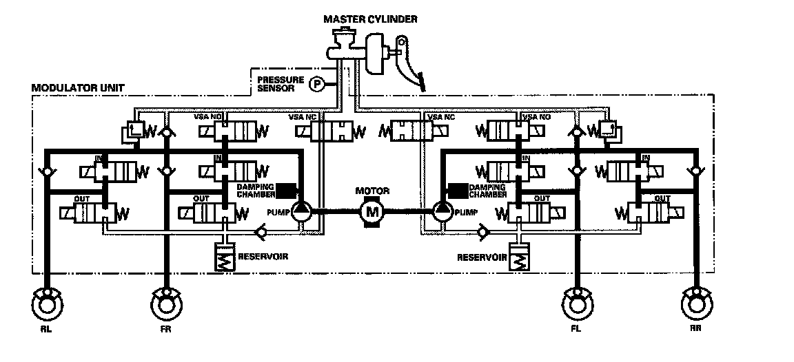
Front and rear caliper fluid is retained by the inlet valve and outlet valve.
Pressure reducing mode
VSA NO valve closed, VSA NC valve open, inlet valve closed, outlet valve open, pump motor ON.
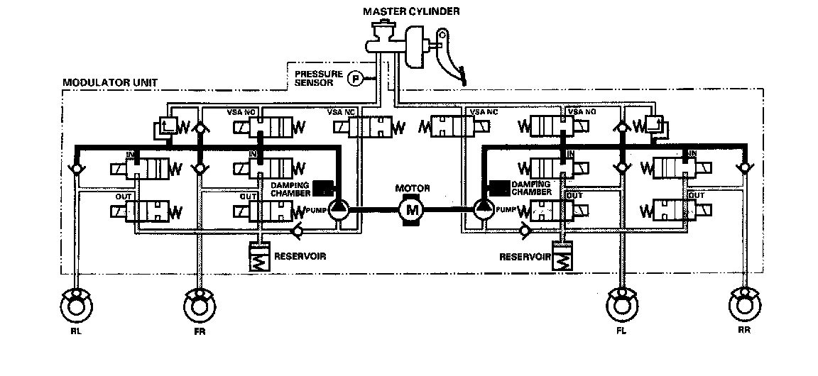
Caliper fluid flows through the outlet valve to the reservoir.