Circuit Test
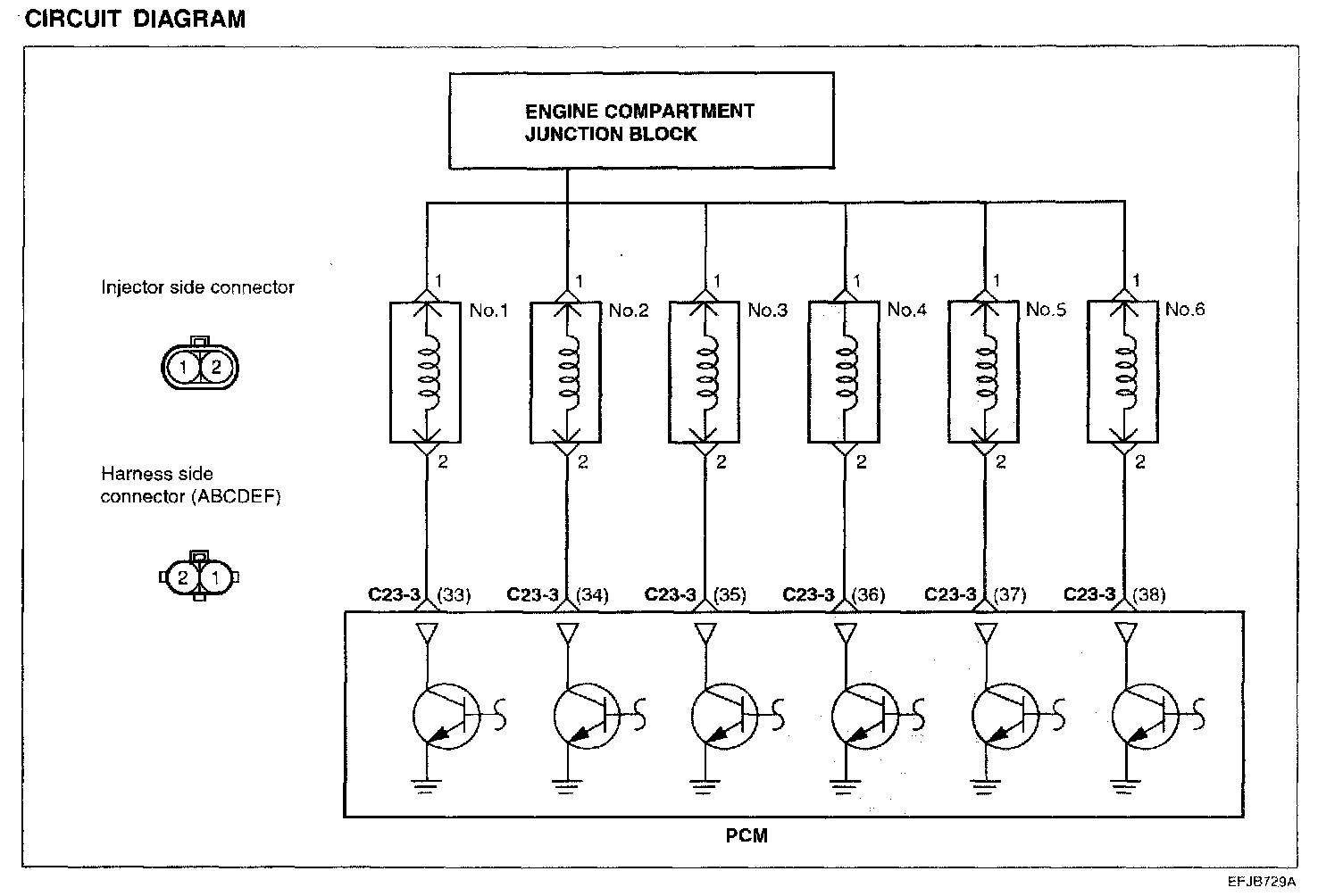
FUEL INJECTORThe injectors inject fuel according to a signal coming from the PCM. The amount of fuel injected by the injectors is determined by the time during which the solenoid valve is energized. The amount of time the solenoid value is energized is determined by the pulse width of the signal from the PCM.
Circuit Diagram:
INJECTOR CHECKING
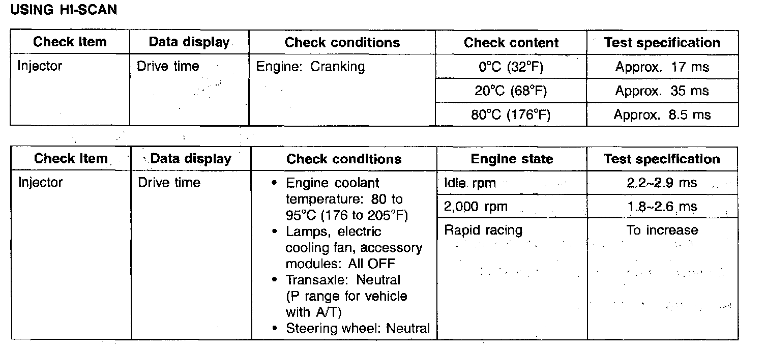
Using Hi-Scan:
NOTE:
1. The injector drive time is when the supply voltage is 11 V and the cranking speed is less than 250 rpm.
2. When engine coolant temperature is lower than 0 °C (32 °F), the PCM fires all four cylinders simultaneously
3. When the vehicle is new (within initial operation of about 500 km [300 miles]), the injector drive time may be about 10% longer
USING STETHOSCOPE AND VOLTMETER
Operation Sound Check
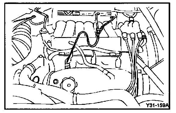
1. Using a stethoscope, check the injectors for a clicking sound at idle. Check that the sound is produced at shorter intervals as the engine speed increases.
NOTE: Ensure that the sound from an adjacent injector is not being transmitted along the delivery pipe to an inoperative injector
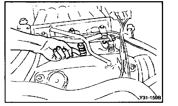
2. If a stethoscope is not available, check the injector operation with your finger. If no vibration is felt, check the wiring connector, injector or injection signal from the PCM.
Resistance Measurement Between Terminals
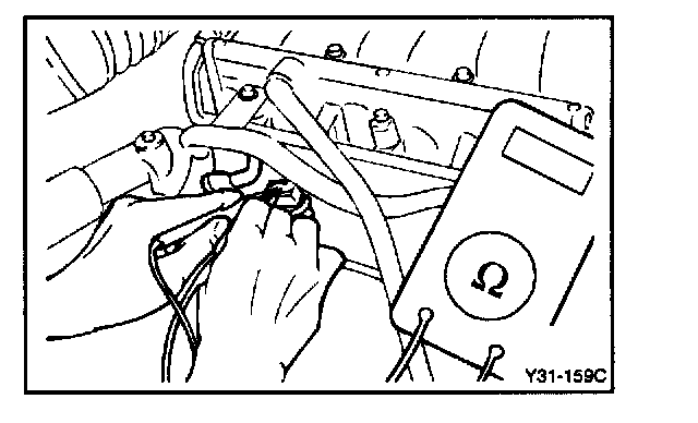
3. Disconnect the connector at the injector.
4. Measure the resistance between terminals.
Standard value: 13 - 16 Ohm [at 20 °C (68 °F)]
5. Re-connect the connector to the injector.
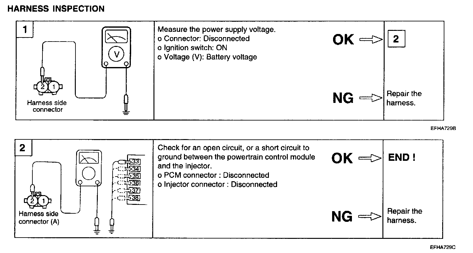
Harness Inspection: