Wheels: Service and Repair
Wheel Alignment
When using commercially available computerized four wheel alignment equipment (caster, camber, toe) to inspect the front wheel alignment, always position the car on a level surface with the front wheels facing straight ahead.
Prior to inspection, make sure that the front suspension and steering system are in normal operating condition and that the wheels and tires face straight ahead and the tires are inflated to the specified pressure.
Toe
Toe is a measurement of how much the front of the wheels are turned in or out from the straight-ahead position.

When the wheels are turned in toward the front of the vehicle, toe is positive (+) (toe in). When the wheels are turned out toward the front of the vehicle, toe is negative(-) (toe out). Toe is measured in degrees, from side to side, and totaled.
[Front]
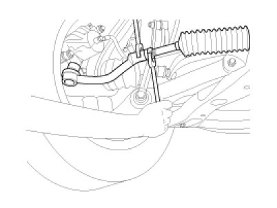
Toe-in(B-A) is adjusted by turning the tie rod turnbuckles. Toe-in on the left front wheel can be reduced by turning the tie rod toward the rear of the car. Toe- in change is adjusted by turning the tie rods for the right and left heels simultaneously at the same amount as follows.
Standard value :
Toe-in
Total : 0°±0.2°
Individual : 0°± 0.1°
NOTE:
- Toe-in adjustment should be made by turning the right and left tie rods at the same amount.
- When adjusting toe-in, loosen the outer bellows clip to prevent twisting the bellows.
- After the adjustment, tighten the tie rod end lock nuts firmly and reinstall the bellows clip.
- Adjust each toe-in to be the range of ±1°.
Tie rod(A) Specified torque :
50 - 55N.m (5 - 5.5kgf.m, 36.2 - 39.8lb-ft)
[Rear]
Standard value :
Toe-in (B-A) (in) : (0.079 ±0.079)
Standard value :
Toe-in
Total : 0.2°±0.2°
Individual : 0.1°± 0.1°
Adjust the toe-in by turning the cam bolt of the assist arm.
Left cam bolt : Clockwise -> toe-in
Right cam bolt : Clockwise -> toe-out
The variation of toe by a rotation of the cam bolt :
About 0.4°
CAUTION:
- Each toe should be within 0.1° ± 0.1°.
If the difference between right and left is not within +0.2°, repeat adjustment.
- After adjusting the cam bolt, tighten the nut to the specified torque.
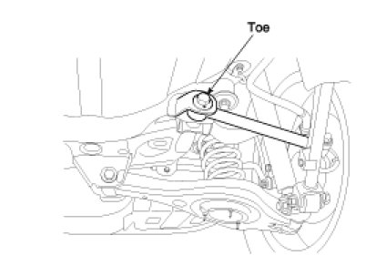
Specified torque
110 - 120N.m (11 - 12kgf.m, 79.5 - 86.8lb-ft)
Camber
[Front]
Camber is the inward or outward tilting of the wheels at the top.
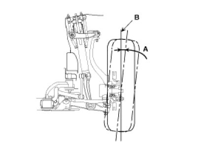

When the wheel tilts out at the top, then the camber is positive (+).
When the wheel tilts in at the top, then the camber is negative(-).
Standard value :0°±0.5°
Difference between right and left angle is within 0.5°
NOTE:
Camber is pre-set at the factory and doesn't need to be adjusted. If the camber is not within the standard value, replace the bent or damaged parts.
[Rear]
Standard value :-0.5°±0.5°
Difference between right and left angle is within 0.5°
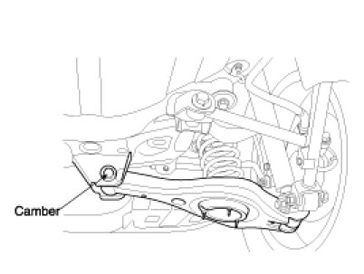
Adjust the camber by turning the cam bolt of the rear lower arm.
Left cam bolt : Clockwise -> camber(+)
Right cam bolt : Clockwise ->camber(-)
The variation of camber by a rotation of the cam bolt :
About 0.2°
Caster
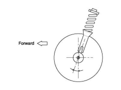
Caster is the tilting of the strut axis either forward or backward from vertical. A backward tilt is positive (+) and a forward tilt is negative (-).
Caster is pre-set at the factory and doesn't need to be adjusted. If the caster is not within the standard value, replace the bent or damaged parts.
Caster :4.83°±1°
NOTE:
- The worn loose or damaged parts of the front suspension assembly must be replaced prior to measuring front wheel alignment.
- Caster are pre-set to the specified value at the factory and don't need to be adjusted.
- If the caster are not within specifications, replace bent or damaged parts.
- The difference of left and right wheels about the the caster must be within the range of 0° ± 0.5°.
Wheel Runout
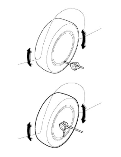
1. Jack up the vehicle and support it with jack stands.
2. Measure the wheel runout with a dial indicator as illustrated.
3. Replace the wheel if the wheel runout exceeds the limit.

Wheel Balance
Removal
1. Remove inner and outer balance weights from the wheel.
CAUTION:
- Be careful not to scratch the wheel during removal procedures.
2. Using releasing agent, remove double-faced adhesive tape from the wheel.
CAUTION:
- Be careful not to scratch the wheel during removal.
- After removing double-faced adhesive tape, wipe clean traces of releasing agent from the wheel.
Adjustment
- If a tire balance machine has adhesion balance weight mode settings and drive-in weight mode setting.
select and adjust a drive-in weight mode suitable for wheels.
1. Set wheel on wheel balancer using the center mark as a guide. Start the tire balance machine.
2. Install balance weight.
CAUTION:
- Do not install the inner balance weight before installing the outer balance weight.
- Before installing the balance weight, be sure to clean the mating surface of the wheel.
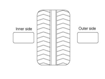
1) Install balance weight in the position shown.
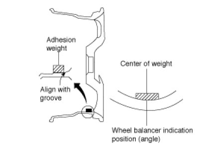
1) When installing balance weight to wheels, set it into the grooved area on the inner wall of the wheel as shown so that the balance weight center is aligned with the wheel balancer indication position (angle).
CAUTION:
- Always use genuine Hyundai adhesion balance weights.
- Balance weights are not reusable; always replace with new ones.
- Do not install one balance weight sheet on top of another.
3. Start wheel balancer again.
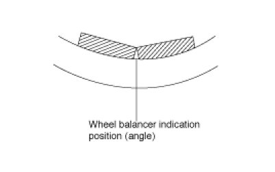
4. Install drive-in balance weight on inner side of road wheel in the wheel balancer indication position (angle).
CAUTION:
Do not install more than two balance weights.
Wheel Nut Tightening
1. Tightening torque.
Tightening torque :
90 - 110N.m (9 - 11kgf.m, 65.1 - 79.5lb-ft)
CAUTION:
When using an impact gun, final tightening torque should be checked using a torque wrench.
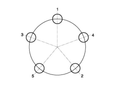
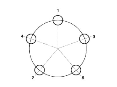
2. Tightening order.
Check the torque again after tightening the wheel nuts diagonally.