Disassembly and Assembly
Caliper Disassembly and Assembly
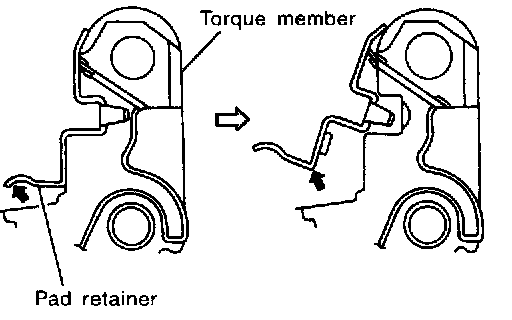
DISASSEMBLY
1. Remove caliper assembly from vehicle.
2. Remove sliding pin bolts from cylinder body, and remove pad, shim, shim cover and pad retainer from torque member.
CAUTION: When removing pad retainer from torque member, lift the pad retainer in the direction shown by arrow (shown in the figure) so as not to deform it.
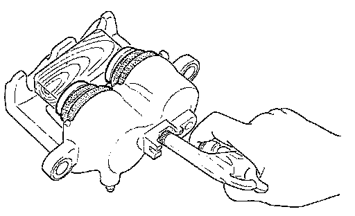
3. Remove sliding pins and sliding pin boots from torque member.
4. Place a wooden block as shown at left, and blow air from union bolt mounting hole to remove pistons and piston boots.
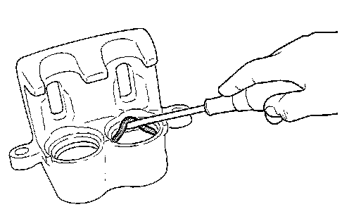
5. Using a slotted screwdriver, remove piston seals from cylinder body.
CAUTION: Be careful not to damage inner wall of cylinder.
CALIPER INSPECTION
Cylinder Body
CAUTION: Use new brake fluid to clean. Never use mineral oils such as gasoline or kerosene.
Check inner wall of cylinder for corrosion, wear, and damage. If a failure is detected, replace cylinder body.
Minor flaws caused by corrosion or a foreign material can be removed by polishing surface with a fine sandpaper. Replace cylinder body, if necessary.
Torque Member
Check for wear, cracks, and damage. If a malfunction is detected, replace applicable part.
Piston
CAUTION: The piston sliding surface is plated. Do not polish with sandpaper.
Check piston surface for corrosion, wear, and damage. If a malfunction is detected, replace applicable part.
Sliding Pin, Pin Bolt, and Pin Boot
Check sliding pin and sliding pin boot for wear, damage, and cracks. If a malfunction is detected, replace applicable part.
DISC ROTOR INSPECTION
Visual Inspection
Check surface of disc rotor for uneven wear, cracks, and serious damage. If a malfunction is detected, replace applicable part.
Run Out Inspection
1. Using wheel nuts, fix disc rotor to wheels hub. (2 or more positions)
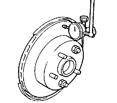
2. Using a dial indicator, check run out.
Measurement point:...................At a point 10 mm (0.394 inch) from outer edge of disc.
Maximum run out:........................0.05 mm (0.002 inch) or less
CAUTION: Before measuring, make sure that axle end play is 0 mm.
3. If run out is outside limit, find the minimum run out point by shifting the mounting positions of disc rotor and wheel hub by one hole.
Thickness Inspection
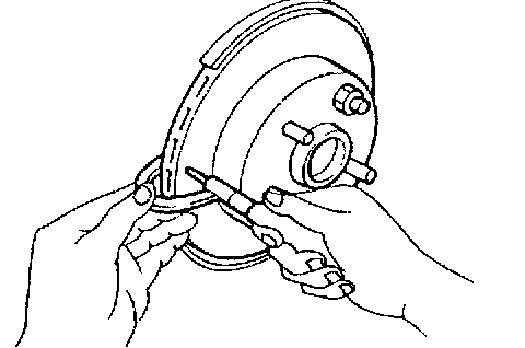
1. Using a micrometer, check thickness of disc rotor. If thickness is outside standard, replace disc rotor.
Standard thickness: 28.0 mm (1.10 inch)
Wear limit: 26.0 mm (1.02 inch)
Maximum uneven wear (measured at 8 positions): 0.015 mm (0.0006 inch) or less
2. If run out is still out of specification, turn rotor with on-car brake lathe("MAD, DL-8700", FIASCO 700 and 705""or equivalent).
FRONT DISC BRAKE:

ASSEMBLY
CAUTION: When assembling, do not use NISSAN rubber grease (KRE00 00010, AKRE00 0001001).
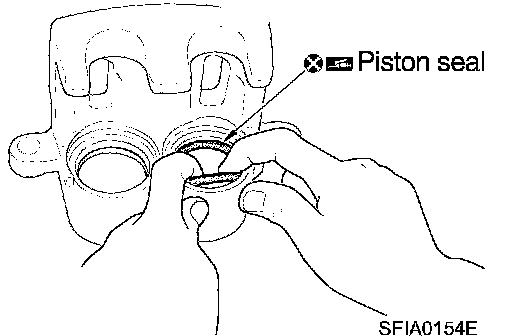
1. Apply rubber lubricant to piston seals, and install them to cylinder body.
CAUTION: Do not reuse piston seals.
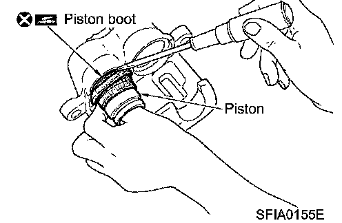
2. Apply brake fluid to piston boots. Cover the piston end with piston boot, and install cylinder-side lip on piston boot properly into groove on cylinder body.
CAUTION: Do not reuse piston boot.
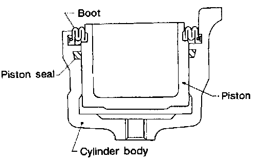
3. Apply brake fluid to piston, and press piston into cylinder body by hand to assemble piston-side lip on piston boot properly into groove on piston.
CAUTION: Press piston evenly and change the pressing point to prevent inner wall of cylinder from being rubbed.
4. Install sliding pins and sliding pin boots to torque member.
5. Install torque member to knuckle spindle and tighten mounting bolts to the specified torque.
CAUTION: Before installing torque member to vehicle, wipe oil and grease on washer seats on knuckle spindle and mounting surface of torque member.
6. Install pad retainers to torque member.
7. After assembling shims and shim covers to pad, install it to torque member.
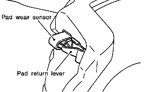
CAUTION: The inner pad and outer pad have pad-return mechanism on upper side of pad retainer. When installing pad, be sure to install pad return lever to pad wear sensor securely shown to left.
8. Install cylinder body, and tighten sliding pin bolt to the specified torque.
9. Install brake hose to cylinder body and tighten union bolts to the specified torque.
CAUTION: Assemble brake hose securely to protrusions on cylinder body.
Do not reuse copper washer for union bolts.
10. After installing caliper assembly, refill with new brake fluid and bleed air.