Fuel Rail: Service and Repair
Fuel Rail Assembly ReplacementRemoval Procedure
IMPORTANT: An 8-digit identification number is located on the fuel rail. Refer to this identification number when servicing or when part replacement is required.
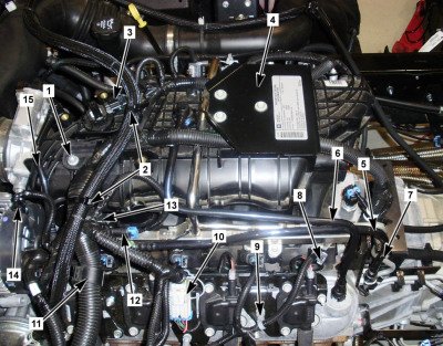
1. Raise the cab
2. Disconnect the negative battery cable.
3. Relieve the fuel system pressure. Fuel Pressure Relief (With CH 48027) Fuel Pressure Relief (Without CH 48027)
4. Remove the engine wiring harness bracket nut (1).
5. Disconnect the engine wiring harness electrical connector (12) from the evaporative emission (EVAP) purge solenoid.
6. Disconnect the engine wiring harness electrical connector (14) from the generator.
7. Disconnect the engine wiring harness electrical connector (3) from the manifold absolute pressure (MAP) sensor.
Left Side of Engine
8. Remove the connector position assurance (CPA) retainer and disconnect the engine wiring harness electrical connector (10) from the ignition coil main electrical connector.
9. Disconnect the engine wiring harness electrical connectors (8) from the fuel injectors, perform the following:
9.1. Mark the connectors to their corresponding injectors to ensure correct reassembly.
9.2. Pull the CPA retainer on the connector up 1 click.
9.3. Push the tab on the connector in.
9.4. Disconnect the fuel injector electrical connector.
Right Side of Engine
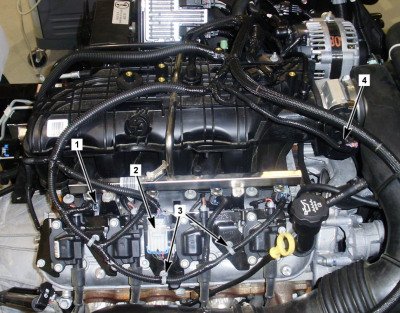
10. Remove the CPA retainer and disconnect the engine wiring harness electrical connector (2) from the ignition coil main electrical connector.
11. Disconnect the engine wiring harness electrical connector (4) from the throttle actuator control module.
12. Disconnect the engine wiring harness electrical connectors (1) from the fuel injectors, perform the following:
12.1. Mark the connectors to their corresponding injectors to ensure correct reassembly
12.2. Pull the CPA retainer on the connector up 1 click.
12.3. Push the tab on the connector in.
12.4. Disconnect the fuel injector electrical connector.
13. Remove the engine wiring harness clip (3) from the ignition coil bracket stud.
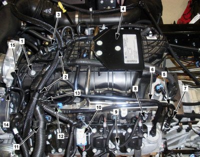
14. Remove the engine wiring harness from the wiring harness bracket clip (16) by sliding it upward while releasing the tab.
15. Remove the two plastic ties (2) that hold the vacuum pump line to the electrical harness.
16. Remove the three emission label plate bolts and remove the emission label plate (4).
17. Gather the branches of the engine wiring harness and reposition it off to the left side.
18. Remove the positive crankcase ventilation (PCV) tube (6).
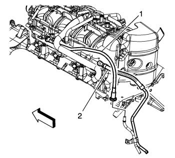
19. Disconnect the chassis fuel feed pipe (2) quick connect fitting from the fuel rail. Metal Collar Quick Connect Fitting Service
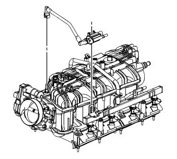
20. Disconnect the EVAP tube quick connect fitting at the intake manifold. Plastic Collar Quick Connection Fitting Service
21. Disconnect the chassis EVAP tube quick connect fitting at the EVAP canister purge solenoid. Plastic Collar Quick Connection Fitting Service
22. Disengage the retainer securing the EVAP canister purge solenoid to the fuel rail.
23. Remove the EVAP tube and EVAP purge solenoid assembly.
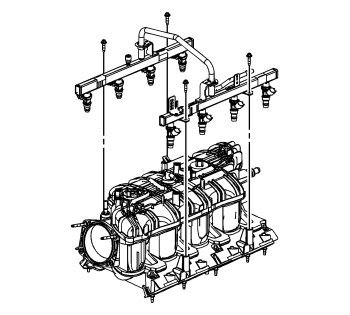
24. Remove the fuel rail bolts.
NOTICE:
- Remove the fuel rail assembly carefully in order to prevent damage to the injector electrical connector terminals and the injector spray tips. Support the fuel rail after the fuel rail is removed in order to avoid damaging the fuel rail components.
- Cap the fittings and plug the holes when servicing the fuel system in order to prevent dirt and other contaminants from entering open pipes and passages.
IMPORTANT:
- Before removal, clean the fuel rail with a spray type engine cleaner, such as GM X-30A or equivalent, if necessary. Follow the package instructions. Do not soak the fuel rail in liquid cleaning solvent.
- Lift evenly on both sides of the fuel rail until all injectors are removed from their bores.
25. Remove the fuel rail assembly.
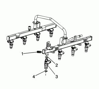
26. Remove the fuel injector retainers (1).
27. Remove the fuel injectors (3) from the fuel rail.
Installation Procedure
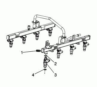
1. Lubricate the NEW fuel injector O-ring seals (2 and 4) with clean engine oil.
2. Install the NEW fuel injector upper and lower O-ring seals (2 and 4) onto the injectors.
3. Install the fuel injectors (3) into the fuel rails.
4. Install the fuel injector retainers (1).
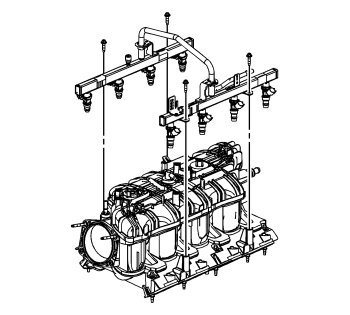
5. Ensure the fuel injector lower O-ring seals are adequately lubricated, if not lubricate the fuel injector lower O-ring seals with clean engine oil.
6. Position the fuel rail onto the intake manifold.
7. Firmly push down on both the centers of the left and right fuel rails, until the rails are fully seated against the intake manifold.
IMPORTANT: Push down firmly on both sides of the rail until all injectors have been seated into their bores.
8. Install the fuel rail bolts.
Tighten
Tighten the bolts to 10 N.m (89 lb in).
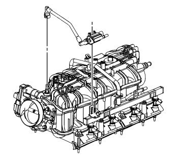
9. Install the EVAP tube to the EVAP canister purge solenoid (if separated).
10. Install the EVAP canister purge solenoid to the fuel rail bracket. Make sure the metal retainer is pushed in towards the EVAP purge solenoid to secure the solenoid in place.
11. Connect the EVAP tube quick connect fitting at the intake manifold. Plastic Collar Quick Connection Fitting Service
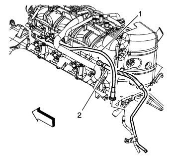
12. Connect the chassis fuel feed pipe (2) quick connect fitting to the fuel rail. Metal Collar Quick Connect Fitting Service
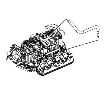
13. Install the PCV tube.
14. Gather the branches of the engine wiring harness and position over the top of the engine.
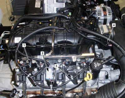
Right Side of Engine
15. Connect the engine wiring harness electrical connector (2) to the ignition coil main electrical connector and install the CPA retainer.
16. Connect the engine wiring harness electrical connector (4) to the throttle actuator control module.
17. Connect the engine wiring harness electrical connectors (1) to the fuel injectors, perform the following:
17.1. Ensure that the CPA retainer is pulled out 1 click.
17.2. Connect the electrical connectors to their corresponding injectors.
17.3. Push the CPA retainer in 1 click.
17.4. Ensure that the connector is secured.
18. Install the engine wiring harness clips (3) to the ignition coil bracket studs.
Left Side of Engine
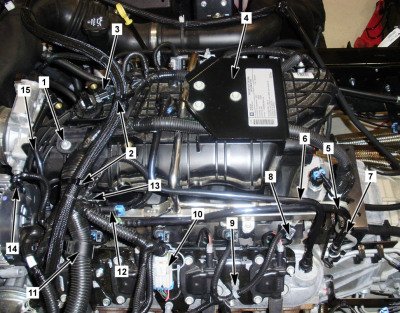
19. Connect the engine wiring harness electrical connector (10) to the ignition coil main electrical connector and install the CPA retainer.
20. Connect the engine wiring harness electrical connectors (8) to the fuel injectors, perform the following:
20.1. Ensure that the CPA retainer is pulled out 1 click.
20.2. Connect the electrical connectors to their corresponding injectors.
20.3. Push the CPA retainer in 1 click.
20.4. Ensure that the connector is secured.
21. Connect the engine wiring harness electrical connector (3) to the MAP sensor.
22. Connect the engine wiring harness electrical connector (14) to the generator.
23. Connect the engine wiring harness electrical connector (12) to the EVAP purge solenoid.
24. Install the wiring harness over the wiring harness bracket clip and install the engine wiring harness bracket nut (1).
Tighten
Tighten the nut to 5 N.m (44 lb in).
25. Install the vacuum line to wire harness ties (2).
26. Install the EVAP tube (5) between the EVAP canister purge solenoid and the EVAP steel chassis line. Plastic Collar Quick Connection Fitting Service and attach the EVAP/fuel line clip (7).
27. Install the emission label plate (4) and attachment bolts.
28. Connect the negative battery cable.
29. Use the following procedure in order to inspect for leaks:
29.1. Turn the ignition ON, with the engine OFF for 2 seconds.
29.2. Turn the ignition OFF for 10 seconds.
29.3. Turn the ignition ON, with the engine OFF.
29.4. Inspect for leaks.
30. Lower the cab.