Hood Latch Panel
Trustmark Authoring Standards (TAS) Repair Procedures
NOTE: TAS style procedures can be identified by steps that have no accompanying step text and the magenta color of the electrical connectors and fasteners such as nuts, bolts, clamps or clips.
A TAS removal and installation procedure uses a sequence of color illustrations to indicate the order to be followed when removing/disassembling or installing/assembling a component.
Specification data
Specification procedures will only contain technical data that is not already part of a repair procedure.
Sequence of tasks
If components must be removed or installed in a specific sequence, the sequence will be identified numerically in a graphic and the corresponding text will be numbered accordingly.
Special Tools, Equipment, Materials and Torque Figures
Special tools will be shown with the tool numbers in the illustration. The special tool numbers, general equipment, materials and torque figures used for the procedure step will be shown in the text column.
TAS Graphics
Colors used in the graphic are as follows:
Blue - Component to be removed/installed or disassembled/assembled.
Green and Brown - Additional components that need to be removed/installed or disassembled/assembled prior to the target component.
Yellow - Component that is touched or affected in a way but remains in the vehicle. It may be detached, attached, moved, modified, checked, adjusted etc.
Magenta - Electrical connectors and fasteners such as nuts, bolts, clamps and clips.
Pale Blue - Special tool(s) and general equipment.


One illustration may have multiple steps assigned to it.
Numbered pointers are used to indicate the number of electrical connectors and fasteners such as nuts, bolts, clamps and clips.
Items in the illustration can be transparent or use cutouts to show hidden details.
Front End Sheet Metal Repairs - Hood Latch Panel
Removal and Installation
Removal
1. NOTE: The hood latch panel is manufactured from mild steel.
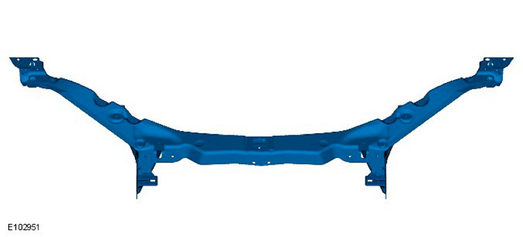
The hood latch panel is serviced as a separate bolt-on panel and includes the left-hand and right-hand fender apron panel front extensions. These are removed and discarded unless damaged.
2. The hood latch panel is replaced in conjunction with:
1. Front bumper cover
2. Front bumper
3. WARNING: The hood latch panel and its associated components form part of the pedestrian protection system, it is essential that any repair or replacement operations do not affect the safe working of the system.
For additional information relating to the pedestrian safety system please see the following:
For additional information, refer to: Pedestrian Protection System.
4. For additional information relating to this repair procedure please see the following:
For additional information, refer to: Health and Safety Precautions / Body Repairs / Corrosion Protection / Body and Frame.
5. Remove the front bumper.
For additional information, refer to: Front Bumper.
6. Remove both headlamp assemblies.
For additional information, refer to: Headlamp Assembly.
7. Remove the condenser core.
For additional information, refer to: Condenser Core - 2.7L Diesel / Condenser Core - 3.0L / Condenser Core - 4.2L, Vehicles Without: Supercharger / Condenser Core - 4.2L, Vehicles With: Supercharger.
8. Remove the radiator.
For additional information, refer to: Radiator / Radiator / Radiator - Vehicles With: Supercharger / Radiator - Vehicles Without: Supercharger.
9. Remove the both hood latch panel braces.
10. Remove the cooling fan upper shroud.
11. Remove both crash sensors.
For additional information, refer to: Crash Sensor.
12. Remove the both hood latches.
13. Remove the hood safety hook guide.
14. Remove both hood latch panel buffers.
15. Release and lay aside the hood latch panel wiring harness.
16. Remove the old panel.

Installation
1. Offer up the new panel. Check alignment, if correct, proceed to next step, if not rectify and recheck before proceeding.
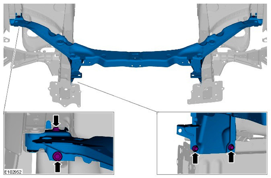
2. Install the hood latch panel.
- Tighten to 10 Nm.
3. The installation of associated panels and components is the reversal of removal procedure.