Removal and Installation
This procedure can be done with the engine in or out of the vehicle.REMOVAL
1. Disconnect negative cable from battery.
WARNING: DO NOT REMOVE THE CYLINDER BLOCK DRAIN PLUGS OR LOOSEN THE RADIATOR DRAIN COCK WITH THE SYSTEM HOT AND PRESSURIZED BECAUSE SERIOUS BURNS FROM THE COOLANT CAN OCCUR.
2. Drain the coolant and disconnect the hoses at the engine thermostat housing. DO NOT waste reusable coolant. If the solution is clean and is being drained only to service the engine or cooling system, drain the coolant into a clean container for reuse.
3. Remove the air cleaner assembly.
4. Remove the engine cylinder head cover.
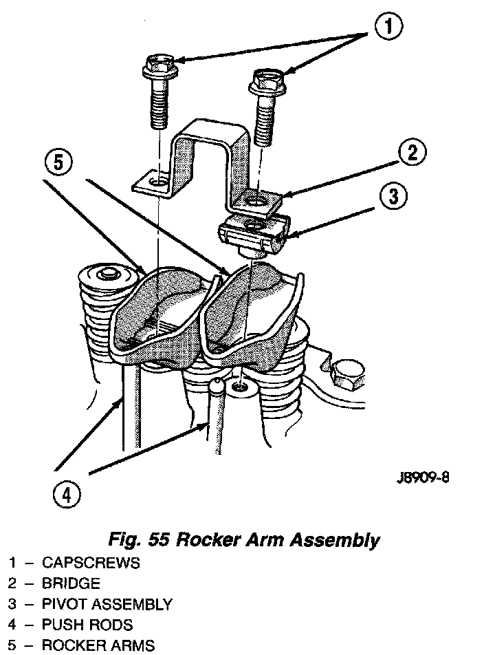
Fig. 55
5. Remove the capscrews, bridge and pivot assemblies and rocker arms (Fig. 55).
6. Remove the push rods. Retain the push rods, bridges, pivots and rocker arms in the same order as removed.
7. Loosen the accessory drive belt at the power steering pump bracket, if equipped or at the idler pulley bracket.
8. If equipped with air conditioning, perform the following:
a. Remove the bolts from the A/C compressor mounting bracket and set the compressor aside.
b. Remove the air conditioner compressor bracket bolts from the engine cylinder head.
c. Loosen the through bolt at the bottom of the bracket.
9. If equipped, disconnect the power steering pump bracket. Set the pump and bracket aside. DO NOT disconnect the hoses.
10. Perform fuel pressure release procedure (Refer to Powertrain Management).
11. Remove the latch clip and disconnect the fuel supply hose.
12. Remove the intake and engine exhaust manifolds from the engine cylinder head.
13. Number and disconnect the ignition wires and remove the spark plugs.
14. Disconnect the coolant temperature sending unit connector.
15. Remove the engine cylinder head bolts.
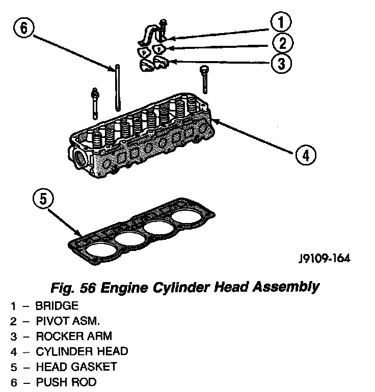
Fig. 56
16. Remove the engine cylinder head and gasket (Fig. 56).
17. If this was the first time the bolts were removed, put a paint dab on the top of the bolt. If the bolts have a paint dab on the top of the bolt or it isn't known if they were used before, discard the bolts.
18. Stuff clean lint free shop towels into the cylinder bores.
NOTE: If valves, springs, or seals are to be inspected/replaced at this time, Refer to Valves and Valve Springs for proper inspection procedures.
INSTALLATION
The engine cylinder head gasket is a composition gasket. The gasket is to be installed DRY. DO NOT use a gasket sealing compound on the gasket.
If the engine cylinder head is to be replaced and the original valves used, measure the valve stem diameter. Only standard size valves can be used with a service replacement engine cylinder head unless the replacement head valve stem guide bores are reamed to accommodate oversize valve stems. Remove all carbon buildup and reface the valves.
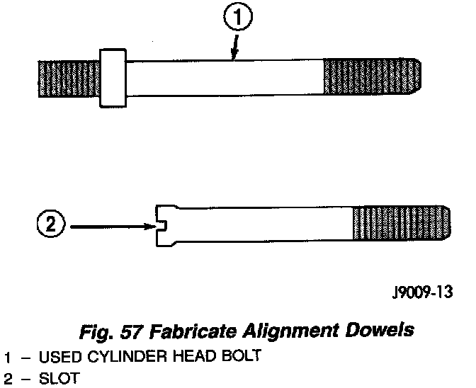
Fig. 57
1. Fabricate two engine cylinder head alignment dowels from used head bolts (Fig. 57). Use the longest head bolt. Cut the head of the bolt off below the hex head. Then cut a slot in the top of the dowel to allow easier removal with a screwdriver.
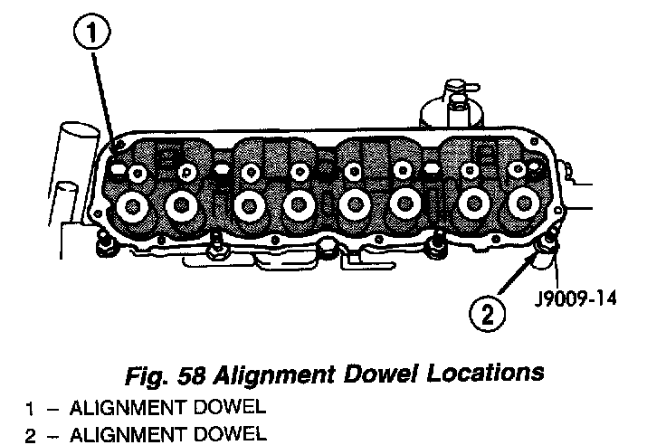
Fig. 58
2. Install one dowel in bolt hole No.10 and the other dowel in bolt hole No.8 (Fig. 58).
3. Remove the shop towels from the cylinder bores. Coat the bores with clean engine oil.
4. Place the engine cylinder head gasket (with the numbers facing up) over the dowels.
5. Place the engine cylinder head over the dowels.
CAUTION: Engine cylinder head bolts should be reused only once. Replace the head bolts if they were used before or if they have a paint dab on the top of the bolt.
6. Coat the threads of bolt No.7, only, with Loctite PST sealant or equivalent.
7. Install all head bolts, except No.8 and No.10.
8. Remove the dowels.
9. Install No.8 and No.10 head bolts.
CAUTION: During the final tightening sequence, bolt No.7 will be tightened to a lower torque than the rest of the bolts. DO NOT overtighten bolt No.7.
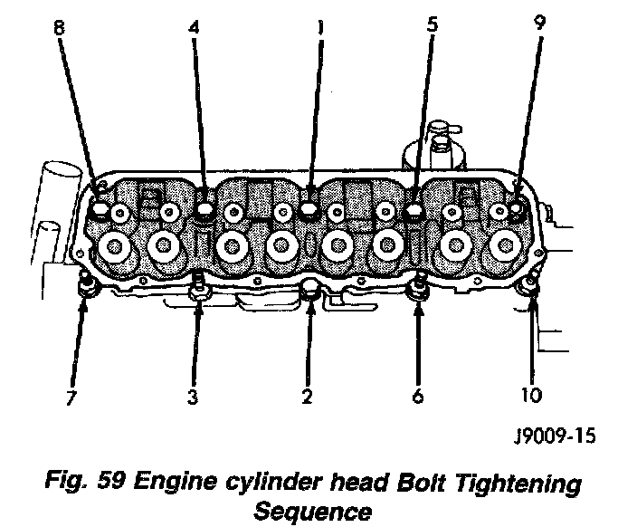
Fig. 59
10. Tighten the engine cylinder head bolts in sequence according to the following procedure (Fig. 59):
a. Tighten all bolts in sequence (1 through 10) to 30 Nm (22 ft. lbs.) torque.
b. Tighten all bolts in sequence (1 through 10) to 61 Nm (45 ft. lbs.) torque.
c. Check all bolts to verify they are set to 61 Nm (45 ft. lbs.) torque.
d. Tighten bolts (in sequence):
- Bolts 1 through 6 to 149 Nm (110 ft. lbs.) torque. Bolt 7 to 136 Nm (100 ft. lbs.) torque.
- Bolts 8 through 10 to 149 Nm (110 ft. lbs.) torque.
e. Check all bolts in sequence to verify the correct torque.
f. If not already done, clean and mark each bolt with a dab of paint after tightening. Should you encounter bolts which were painted in an earlier service operation, replace them.
11. Connect the coolant temperature sending unit connector.
12. Install the spark plugs and tighten to 37 Nm (27 ft. lbs.) torque. Connect the ignition wires.
13. Install the intake and exhaust manifolds.
14. Install the fuel supply line. Push until a "click" is heard. Reinstall latch clip.
15. If equipped attach the power steering pump and bracket.
16. Install the push rods, rocker arms, pivots and bridges in the order they were removed.
17. Install the engine cylinder head cover.
18. Attach the air conditioning compressor mounting bracket to the engine cylinder head and block. Tighten the bolts to 40 Nm (30 ft. lbs.) torque.
19. Attach the air conditioning compressor to the bracket. Tighten the bolts to 27 Nm (20 ft. lbs.) torque.
CAUTION: The accessory drive belt must be routed correctly. Incorrect routing can cause the water pump to turn in the opposite direction causing the engine to overheat.
20. Install the accessory drive belt and correctly tension the belt.
21. Install the air cleaner assembly.
22. Connect the hoses to the thermostat housing and fill the cooling system to the specified level (Refer to Cooling System).
23. Install the coolant temperature sending unit connector.
24. Connect negative cable to battery.
25. Connect the upper radiator hose and heater hose at the thermostat housing.
26. Fill the cooling system. Check for leaks.
WARNING: USE EXTREME CAUTION WHEN THE ENGINE IS OPERATING. DO NOT STAND IN DIRECT LINE WITH THE FAN. DO NOT PUT HANDS NEAR THE PULLEYS, BELTS OR FAN. DO NOT WEAR LOOSE CLOTHING.
27. Operate the engine with the radiator cap off. Inspect for leaks and continue operating the engine until the thermostat opens. Add coolant, if required.
CYLINDER HEAD
DISASSEMBLY
1. Use Valve Spring Compressor Tool MD-998772A and compress each valve spring.
2. Remove the valve locks, retainers, springs and valve stem oil seals. Discard the oil seals.
3. Use an Arkansas smooth stone or a jewelers file to remove any burrs on the top of the valve stem, especially around the groove for the locks.
4. Remove the valves, and place them in a rack in the same order as removed.
ASSEMBLY
1. Thoroughly clean the valve stems and the valve guide bores.
2. Lightly lubricate the stem.
3. Install the valve in the original valve guide bore.
4. Install the replacement valve stem oil seals on the valve stems. If the 0.381 mm (0.015 inch) oversize valve stems are used, oversize oil seals are required.
5. Position the valve spring and retainer on the engine cylinder head and compress the valve spring with Valve Spring Compressor Tool MD-998772A.
6. Install the valve locks and release the tool.
7. Tap the valve spring from side to side with a hammer to ensure that the spring is properly seated at the engine cylinder head. Also tap the top of the retainer to seat the valve locks.