Brake Lamp Switch
OVERVIEW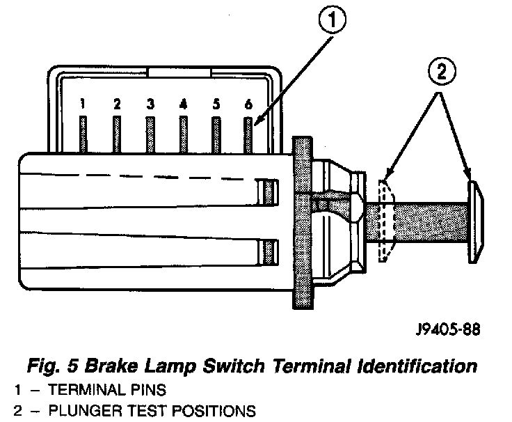
Brake lamp switch operation can be tested with an ohmmeter. The ohmmeter is used to check continuity between the pin terminals at different plunger positions .
SWITCH CIRCUIT IDENTIFICATION
- Terminals 1 and 2: brake sensor circuit
- Terminals 3 and 4: speed control circuit
- Terminals 5 and 6: brake lamp circuit
SWITCH CONTINUITY TEST
NOTE: Disconnect switch harness before testing continuity.
With the switch plunger retracted, attach test leads to terminal pins 1 and 2. Replace switch if meter indicates no continuity.
With the switch plunger retracted, attach test leads to terminal pins 3 and 4. Replace switch if meter indicates no continuity.
With the switch plunger extended, attach test leads to terminal pins 5 and 6. Replace switch if meter indicates no continuity.