Instruments - Inaccurate Outside Temperature Display
ELECTRICALEL015-03
Title:
OUTSIDE TEMPERATURE
DISPLAY INACCURATE
Models:
'03 GX 470
November 26, 2003
Introduction
Some customers with 2003 model year GX 470 vehicles may experience a condition where the outside temperature display may indicate an incorrect value. An updated accessory meter has been made available to address this condition.
Applicable Vehicles
^ 2003 model year GX 470 vehicles produced BEFORE the Production Change Effective VIN shown below.

Production Change Information
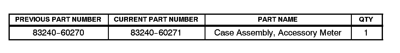
Parts Information
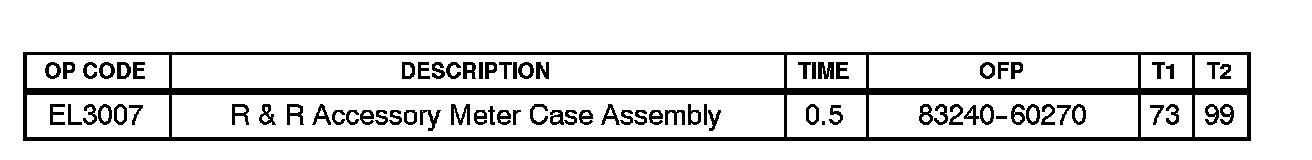
Warranty Information
Applicable Warranty * :
This repair is covered under the Lexus Comprehensive Warranty. This warranty is in effect for 48 months or 50,000 miles, whichever occurs first, from the vehicle's in-service date.
* Warranty application is limited to correction of a problem based upon a customer's specific complaint.
Repair Procedure
1. Make a Note of the Radio Presets
2. Remove Console Upper Panel Garnish No. 2
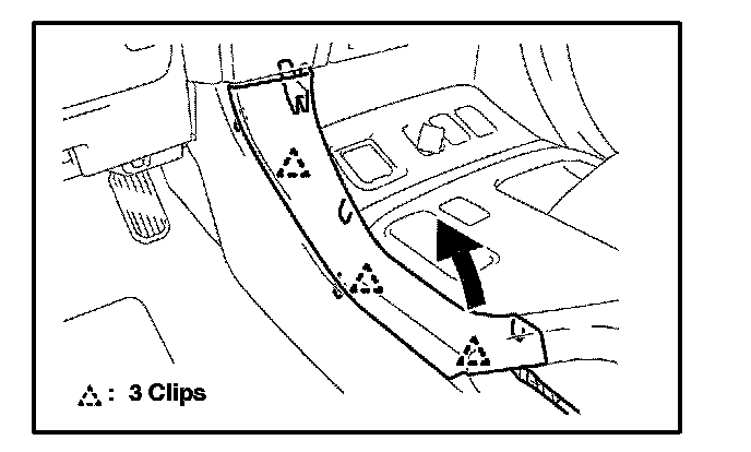
A. Disengage the 3 clips and remove the console upper panel garnish No. 2.
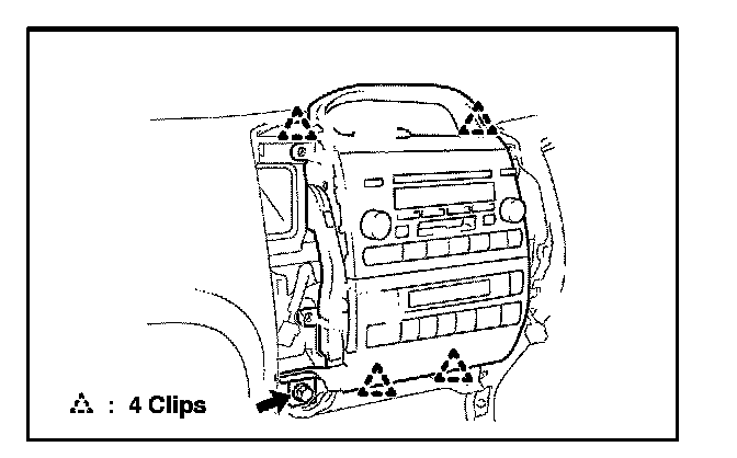
3. Remove Console Upper Panel Garnish No. 1
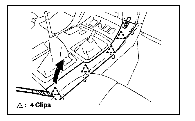
A. Disengage the 4 clips and remove the console upper panel garnish No. 1.
4. Remove Instrument Panel Garnish Sub-Assembly LH and RH
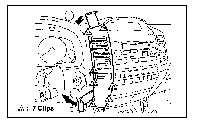
A. Using a nylon removal tool, disengage the 7 clips as shown in the illustration.
B. Disconnect the connector and remove the instrument panel garnish sub-assembly.
5. Remove Instrument Cluster Finish Panel Center Lower
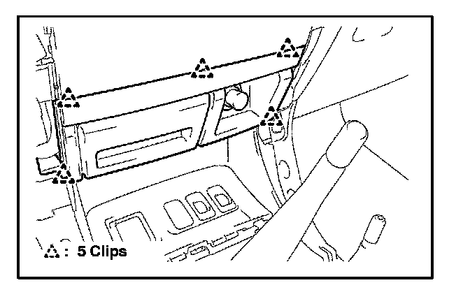
A. Disengage the 5 clips and remove the instrument cluster finish panel center lower, then disconnect the connectors.
6. Unbolt the Integration Control and Panel Assembly
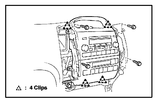
A. Remove the 4 bolts securing the integration control and panel assembly.
B. Pull on the integration control panel to disengage the 4 clips.
7. Confirm Integrity of the Ambient Temperature Sensor Circuit
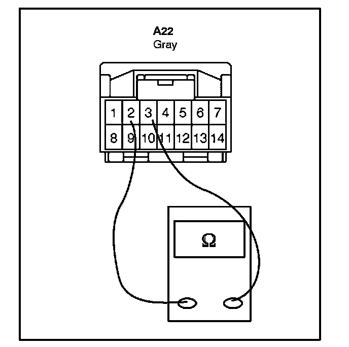
A. Unplug the accessory meter connector and measure the resistance between terminals 2 and 3.
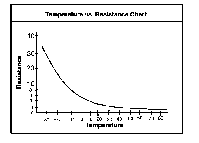
a. If the resistance is with in specification, proceed to step 8.
b. If the resistance is not with in specification, diagnose and repair the ambient temperature sensor circuit.
8. Unplug the Integration Control and Panel Main Connector at the Bottom Left Hand Side and Remove the Integration Control and Panel
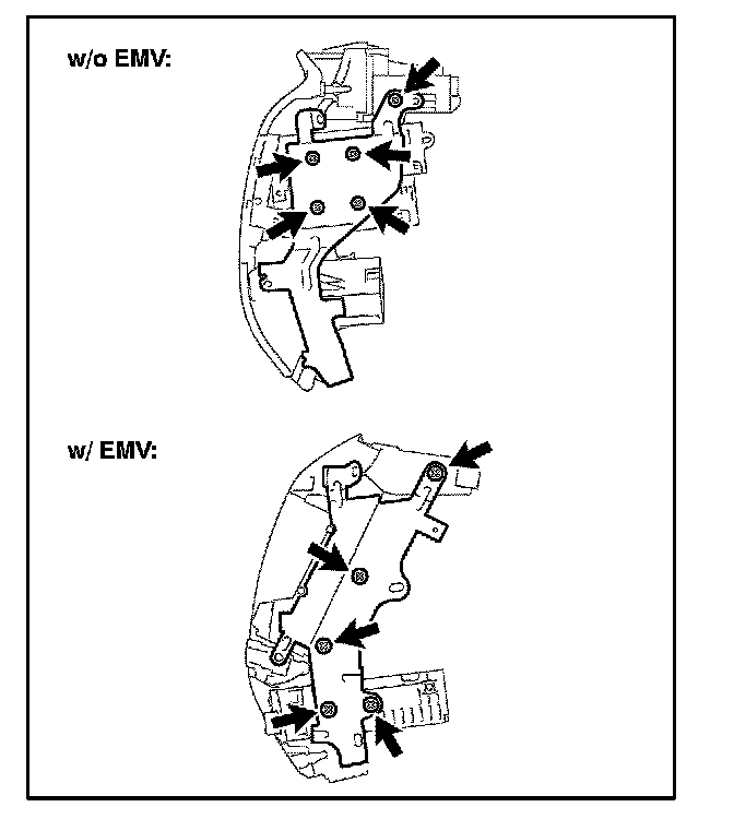
9. Remove Radio Bracket No. 1
A. Remove the 5 screws.
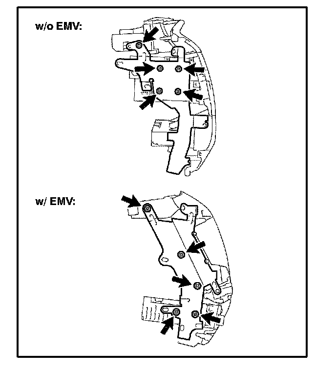
10. Remove Radio Bracket No. 2
A. Remove the 5 screws.
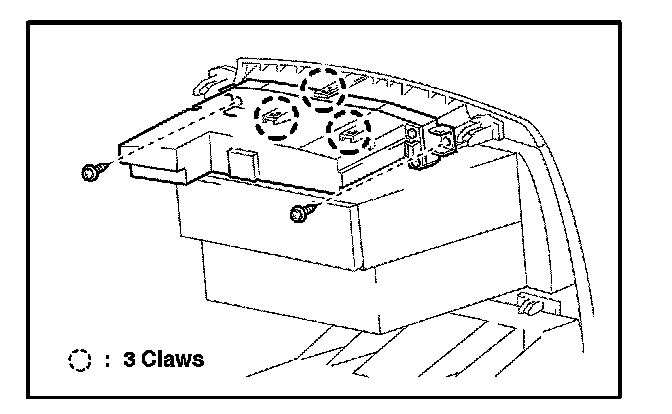
11. Remove Accessory Meter Assembly
A. Remove the 2 screws.
B. Disengage the 3 claws and remove the accessory meter assembly.
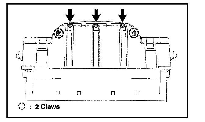
12. Remove Accessory Meter Switch
A. Remove the 3 screws.
B. Disengage the 2 claws.
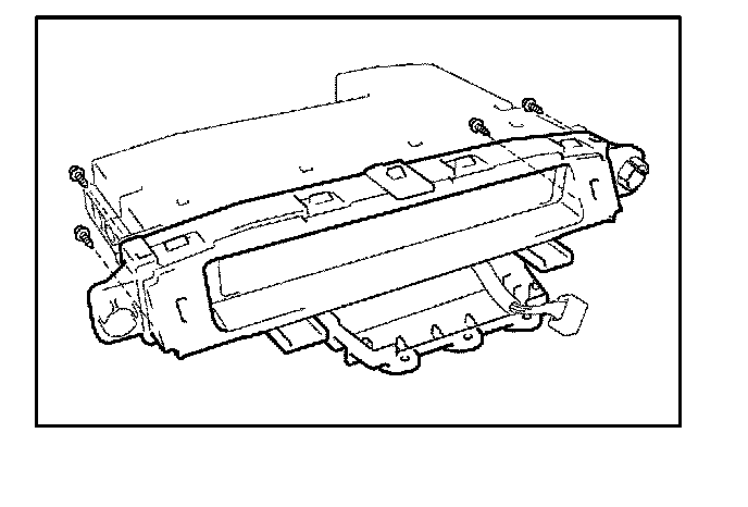
13. Remove Accessory Meter Case Assembly
A. Remove the 4 screws and accessory meter case assembly.
14. Install New Accessory Meter Case Assembly and Reassemble in Reverse Order of Disassembly
15. Reprogram Radio Presets and Set Clock on Accessory Meter