Part 3
ENGINE ASSEMBLY - 2.5L
CAUTION:Only hand-tighten the bolt or damage to the front cover can occur.
76. Using the 6 mm x 18 mm bolt, check the position of the crankshaft pulley.
- If it is not possible to install the bolt, the engine valve timing must be corrected.

77. Install the Camshaft Alignment Plate to check the position of the camshafts.
- If it is not possible to install the Camshaft Alignment Plate, the engine valve timing must be corrected.
78. Remove the Camshaft Alignment Plate.

79. Install the Crankshaft Position (CKP) sensor and the 2 bolts.
- Do not tighten the bolts at this time.

80. Using the Crankshaft Sensor Aligner, adjust the CKP sensor.
- Tighten the 2 CKP sensor bolts to 7 Nm {0.7 kgf-m, 62 in-lbf}.

81. Remove the 6 mm x 18 mm bolt.

82. Remove the Crankshaft TDC Timing Peg.

83. Install the engine plug bolt.
- Tighten to 20 Nm {2.0 kgf-m, 177 in-lbf}.
CAUTION:Do not use metal scrapers, wire brushes, power abrasive discs or other abrasive means to clean the sealing surfaces. These tools cause scratches and gouges which make leak paths.
84. Clean the valve cover gasket surface with metal surface cleaner.

85. Apply silicone gasket and sealant to the locations shown.
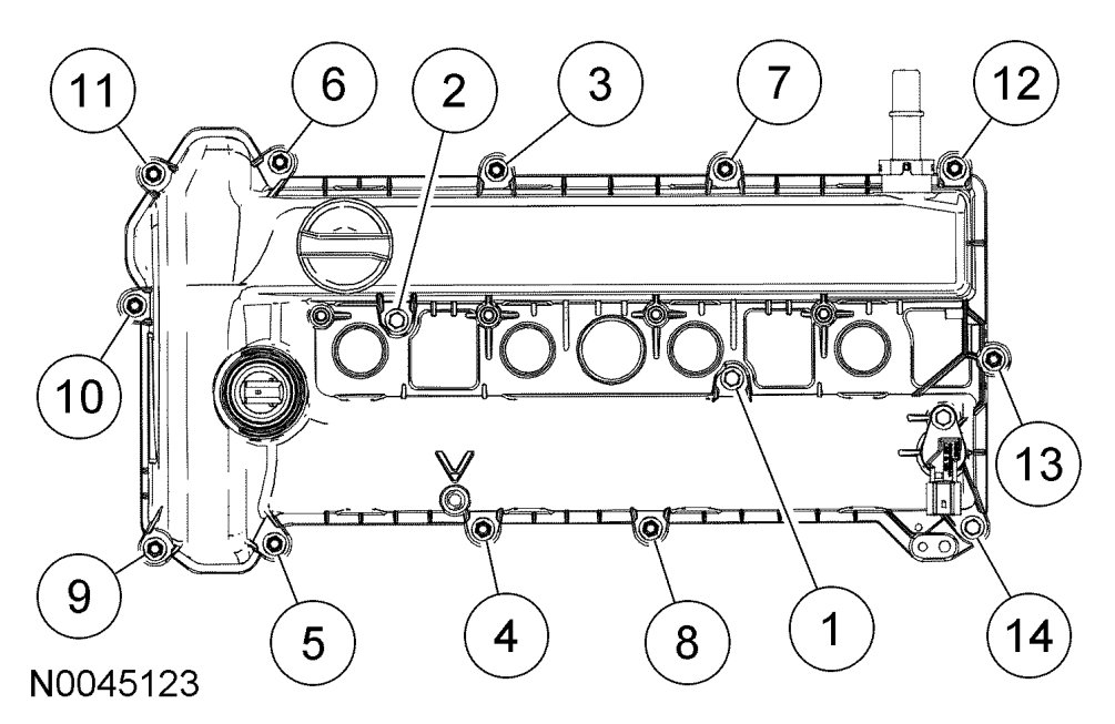
86. Install the valve cover.
- Tighten the bolts in the sequence shown to 10 Nm {1.0 kgf-m, 89 in-lbf}.
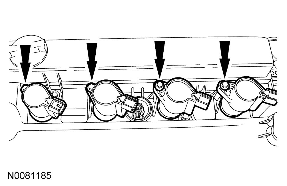
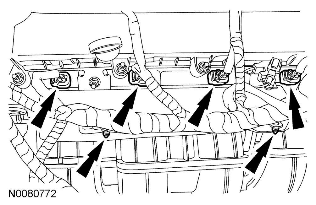
87. Install the 4 coil-on-plugs and the 4 bolts
- Tighten to 8 Nm {0.8 kgf-m, 71 in-lbf}.

NOTE:Make sure the notch on the oil level indicator is aligned with the V-shaped boss on the valve cover and fully engaged into the valve cover.
88. Install the oil level indicator.

89. If equipped, install the block heater.
- Tighten to 40 Nm {4.1 kgf-m, 71 ft-lbf}.

90. Install the crankcase vent oil separator and the 8 bolts.
- Tighten to 10 Nm {1.0 kgf-m, 89 in-lbf}.

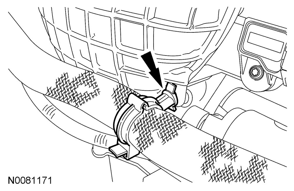
NOTE:The Knock Sensor (KS) must not touch the crankcase vent oil separator.
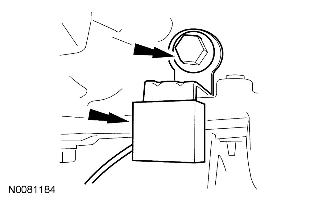
91. Install the KS and the bolt.
- Tighten to 20 Nm {2.0 kgf-m, 177 in-lbf}.
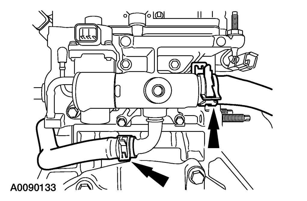
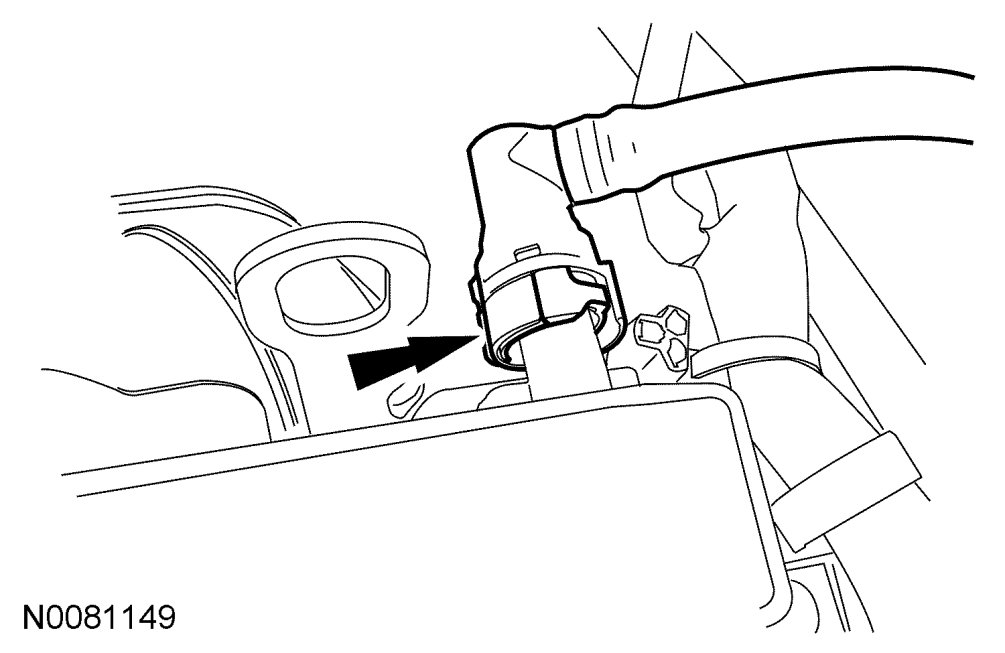
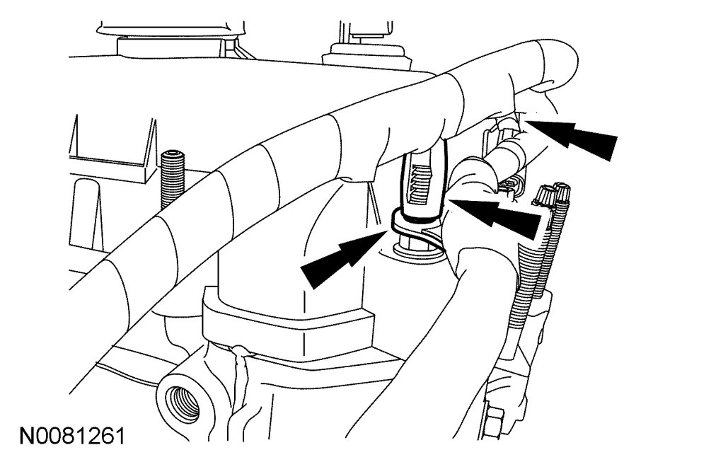
92. Install the 2 coolant hoses.
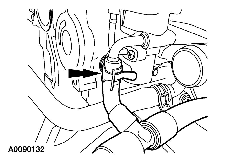
93. Install the coolant hose.

94. Install the coolant hose.

95. Install the EGR tube.
- Tighten to 55 Nm {5.6 kgf-m, 41 ft-lbf}.

CAUTION:If the engine is repaired or replaced because of upper engine failure, typically including valve or piston damage, check the intake manifold for metal debris. If metal debris is found, install a new intake manifold. Failure to follow these instructions can result in engine damage.
96. Position the intake manifold and connect the crankcase vent oil separator tube.
NOTE:Inspect and install new intake manifold gaskets, if necessary.
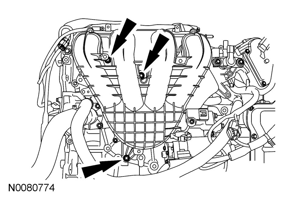
97. Install the intake manifold gaskets, intake manifold and the 8 bolts.
- Tighten to 18 Nm {1.8 kgf-m, 159 in-lbf}.

CAUTION:Use O-ring seals that are made of special fuel-resistant material. Use of ordinary O-rings can cause the fuel system to leak. Do not reuse the O-ring seals.
98. Install new fuel injector O-rings.
- Separate the fuel injectors from the fuel rail.
- Remove and discard the fuel injector O-rings.
- Install new O-rings and lubricate with clean engine oil.
- Install the fuel injectors onto the fuel rail.
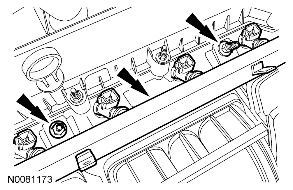
99. Install the fuel rail with the fuel injectors as an assembly and the 2 stud bolts.
- Tighten to 23 Nm {2.3 kgf-m, 17 ft-lbf}.
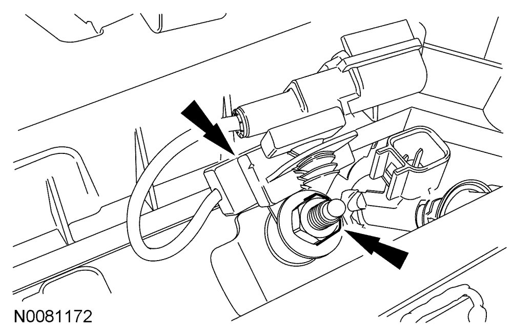
100. Install the radio capacitor and nut.
- Tighten to 10 Nm {1.0 kgf-m, 89 in-lbf}.
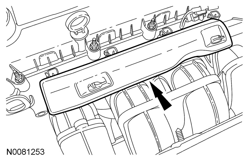
101. Install the fuel rail insulator.
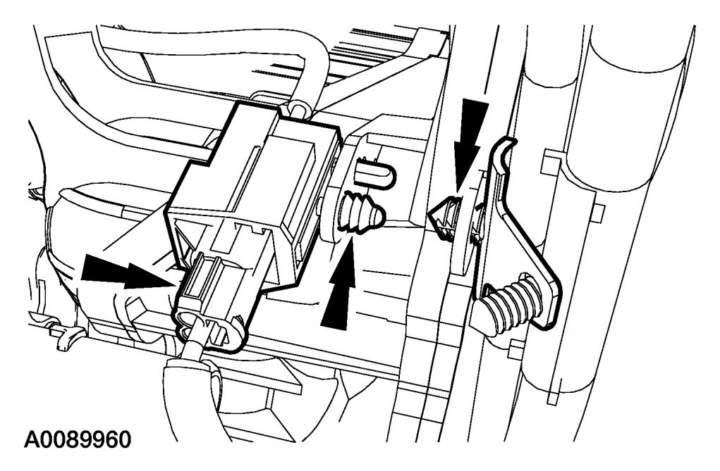
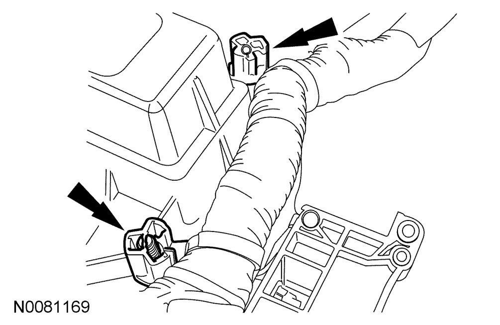
102. Connect the 4 fuel injector electrical connectors. Attach the 2 wiring harness retainers.
103. Connect the radio capacitor electrical connector.

104. Position the engine control wiring harness on the engine and connect the CHT sensor and install the rubber boot.
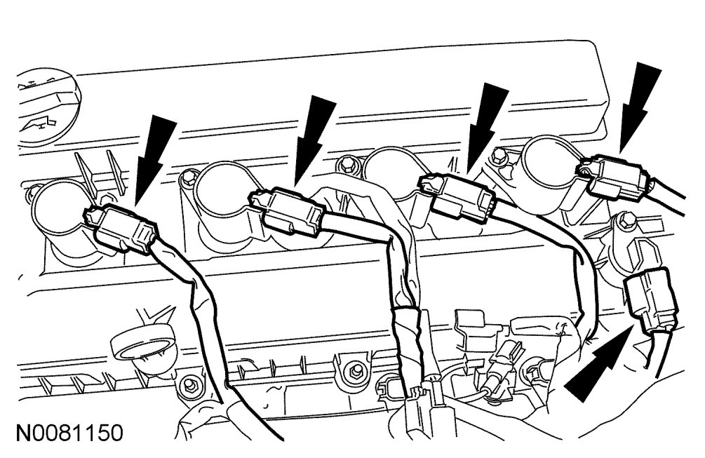
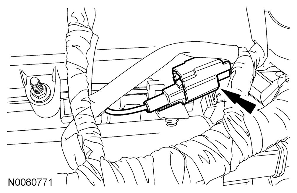
105. Connect the 4 coil-on-plugs and Camshaft Position (CMP) sensor electrical connectors.
106. Attach all wiring harness retainers to the intake manifold.
107. Connect the KS and attach the 2 wiring harness retainers.
108. Connect the EGR valve electrical connector.
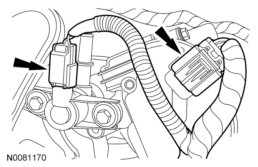
109. Connect the electronic throttle control and Evaporative Emission (EVAP) canister purge valve electrical connectors.
110. Connect the Manifold Absolute Pressure (MAP) sensor electrical connector.
111. Attach the wiring harness retainers to the LH side valve cover stud bolts.
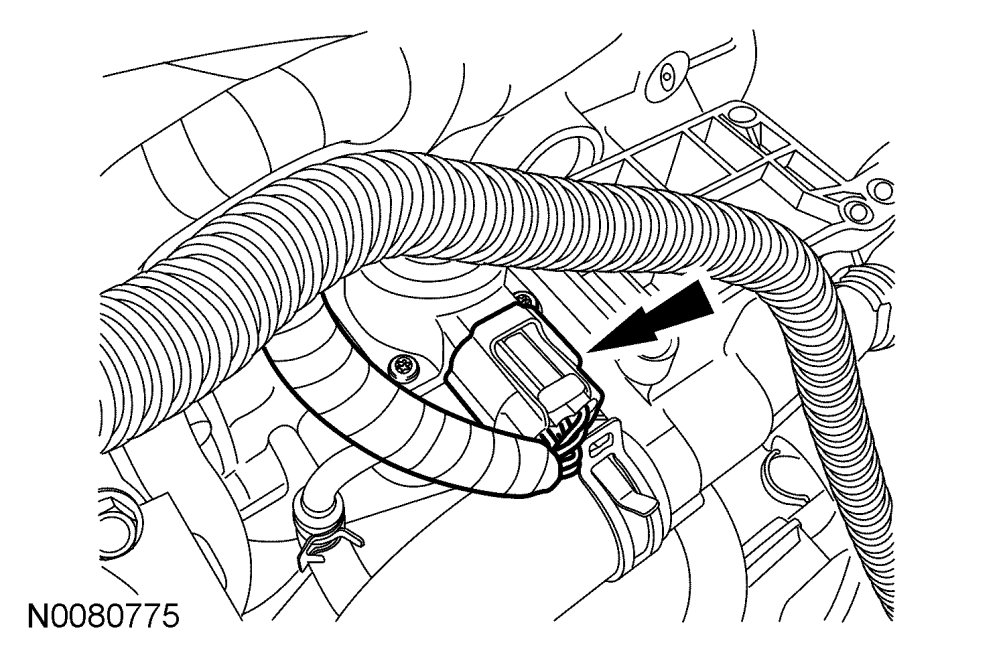
112. Connect the crankcase vent hose to the valve cover.
113. Attach the wiring harness retainers to the RH side valve cover stud bolts.
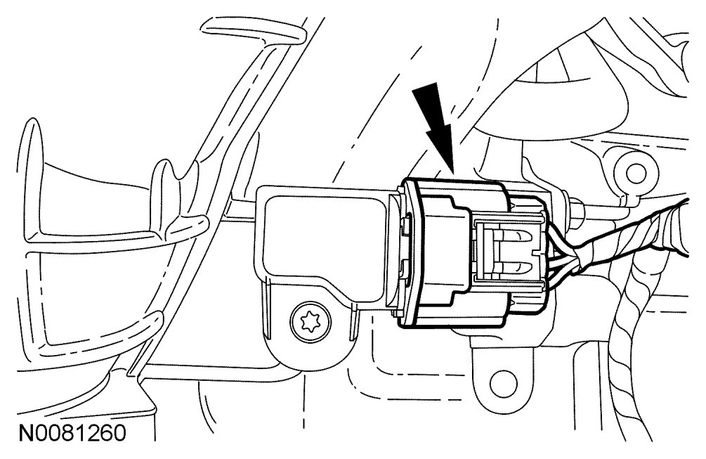
114. Connect the VCT electrical connector.
115. If removed, install the capacitor and bolt.
- Tighten to 20 Nm {2.0 kgf-m, 177 in-lbf}

NOTE:Clean the gasket mating surfaces with metal surface prep.
116. Install the oil filter adapter with a new gasket.
- Tighten to 25 Nm {2.5 kgf-m, 18 ft-lbf}.
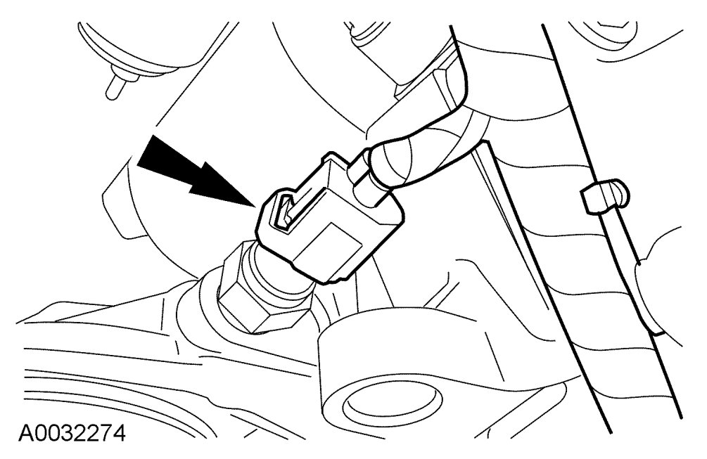
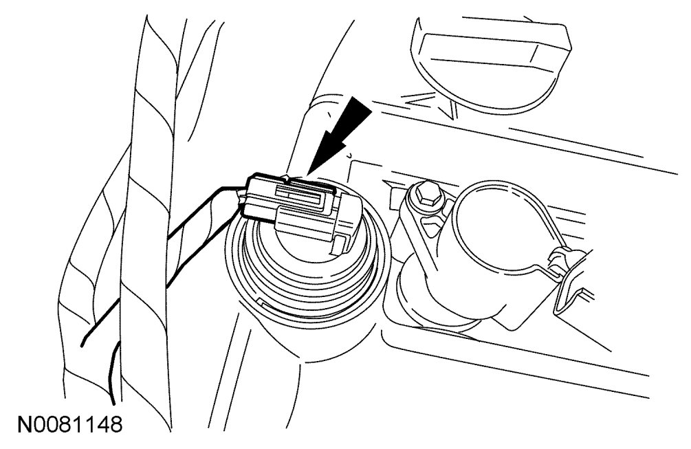
117. Connect the Engine Oil Pressure (EOP) switch electrical connector.
118. Install the coolant tube retainer to the intake manifold.
119. Install the thermostat housing and bolts
- Tighten to 10 Nm {1.0 kgf-m, 89 in-lbf}.

NOTE:Clean the coolant pump mating surface with metal surface prep.
NOTE:Lubricate the coolant pump O-ring with clean engine coolant.
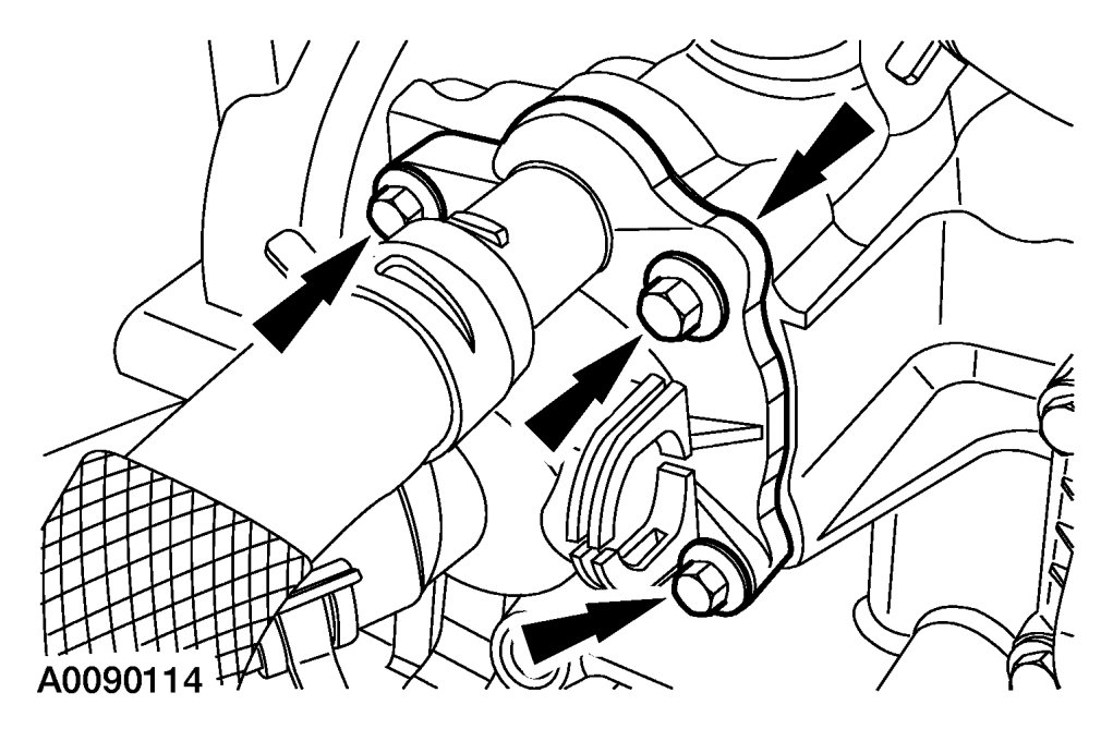
120. Install the coolant pump and bolts.
- Tighten to 10 Nm {1.0 kgf-m, 89 in-lbf}.

121. Install the 3 coolant pump pulley and bolts.
- Tighten to 20 Nm {2.0 kgf-m, 177 in-lbf}.
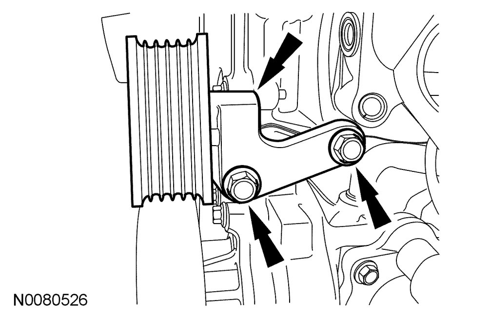
122. Install the accessory drive belt idler pulley and bracket and the 2 bolts.
- Tighten to 25 Nm {2.5 kgf-m, 18 ft-lbf}.
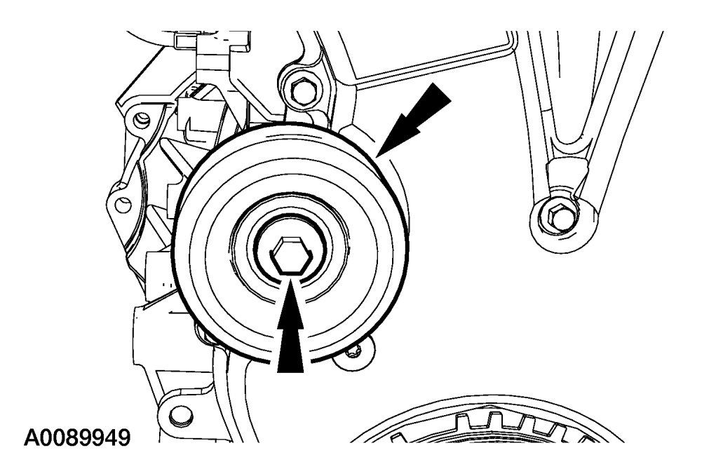
123. Install the accessory drive belt idler pulley.
- Tighten to 25 Nm {2.5 kgf-m, 18 ft-lbf}.
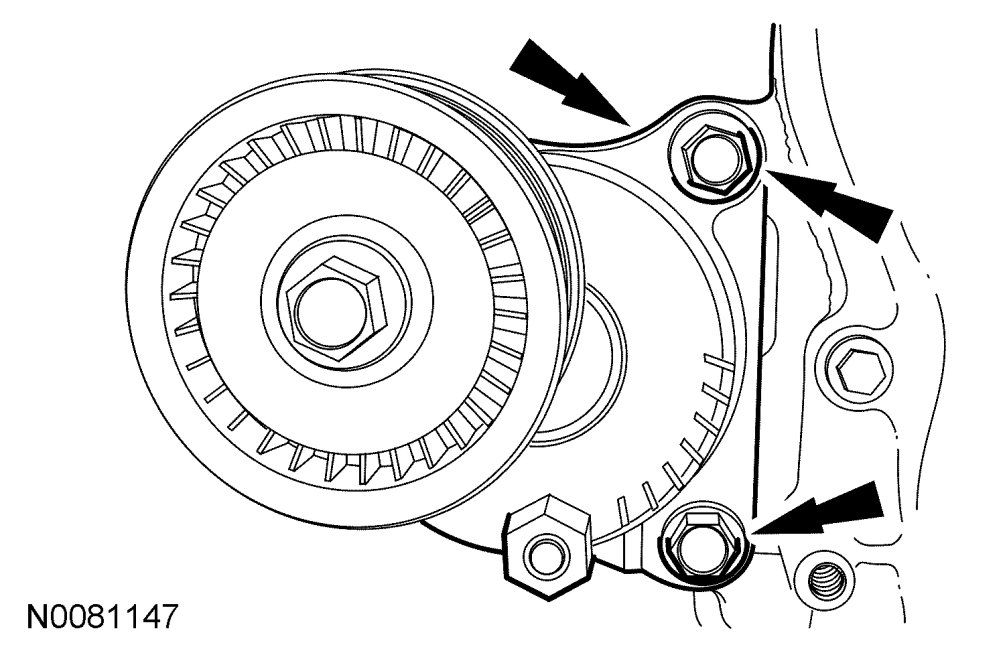
124. Install the accessory drive belt tensioner and the 2 bolts.
- Tighten to 25 Nm {2.5 kgf-m, 18 ft-lbf}.

125. Install 7 new exhaust manifold studs in the cylinder head.
- Tighten to 17 Nm {1.7 kgf-m, 150 in-lbf}.
126. Install the new exhaust manifold gasket on the engine.
CAUTION:Failure to tighten the exhaust manifold nuts to specification a second time will cause the exhaust manifold to develop an exhaust leak.
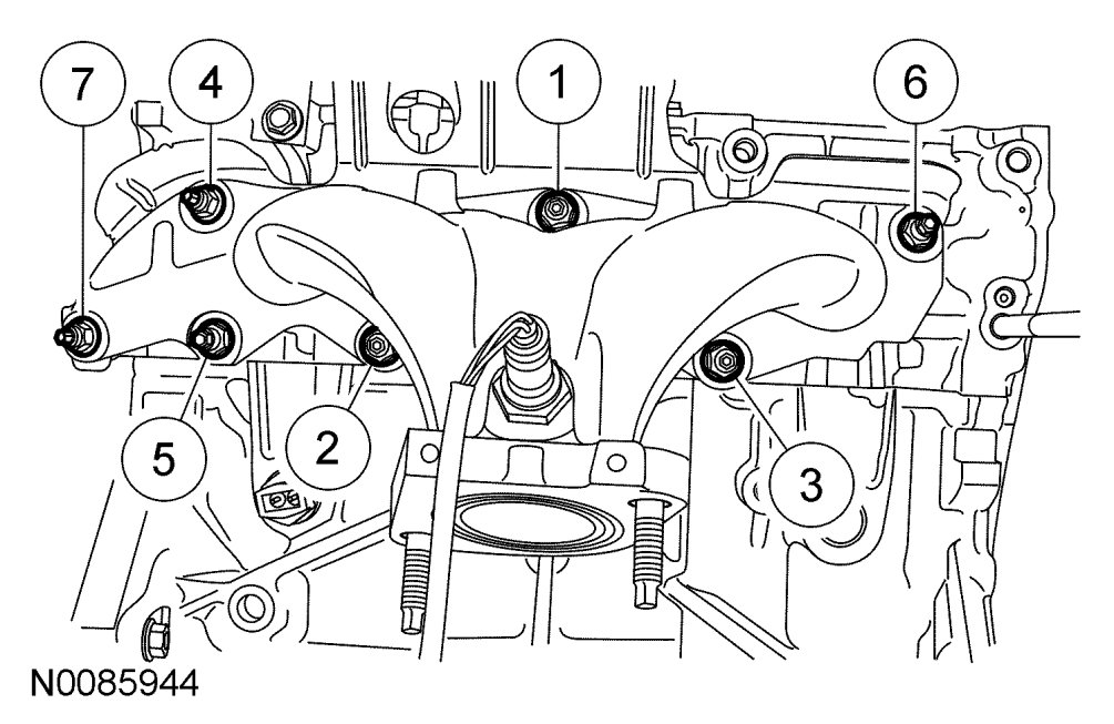
NOTE:Make sure to tighten the nuts in the sequence shown in 2 stages.
127. Position the exhaust manifold and tighten the 7 new exhaust manifold nuts in the sequence shown in 2 stages:
- Stage 1: Tighten to 48 Nm {4.9 kgf-m, 35 ft-lbf}.
- Stage 2: Tighten to 48 Nm {4.9 kgf-m, 35 ft-lbf}.
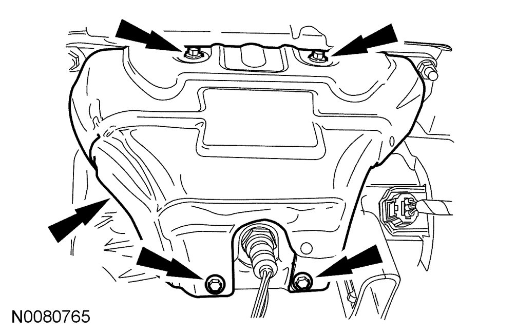
128. Install the exhaust manifold heat shield and the 4 bolts.
- Tighten to 10 Nm {1.0 kgf-m, 89 in-lbf}.
129. Connect the Heated Oxygen Sensor (HO2S) electrical connector.
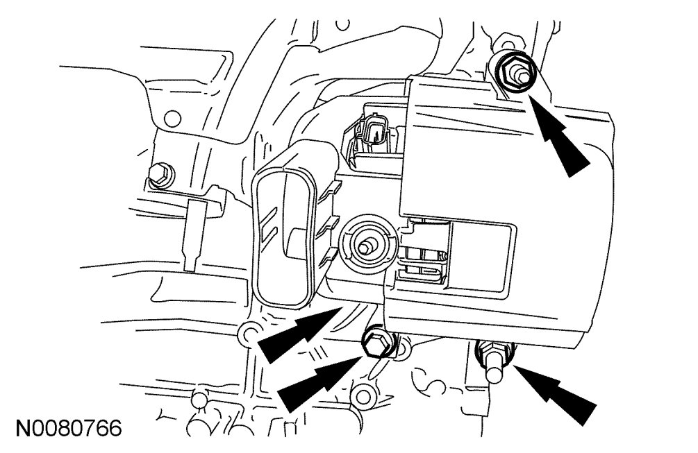
130. Install the generator, 2 nuts and 1 bolt.
- Tighten to 47 Nm {4.8 kgf-m, 35 ft-lbf}.
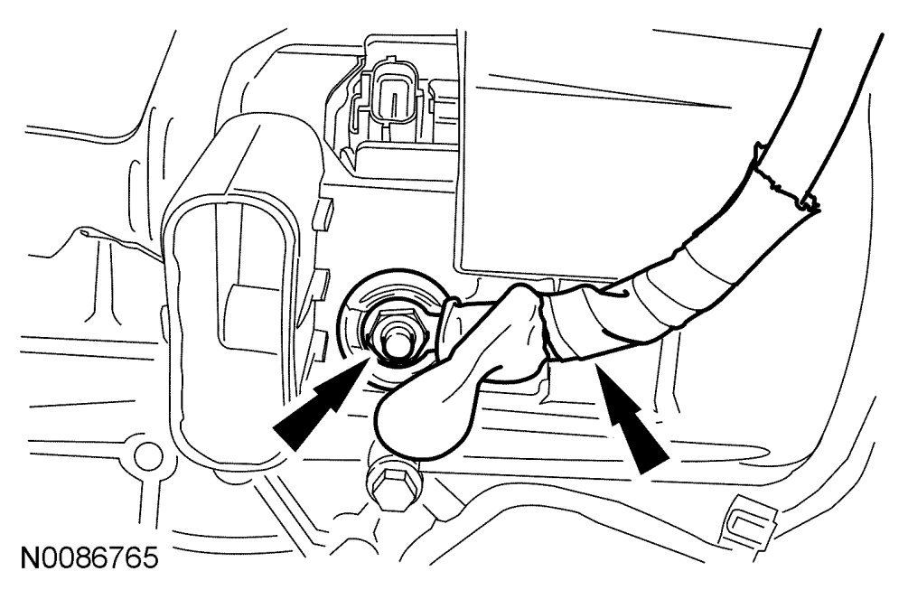
131. Connect the generator electrical connection and install the nut.
- Tighten to 6 Nm {0.6 kgf-m, 53 in-lbf}.
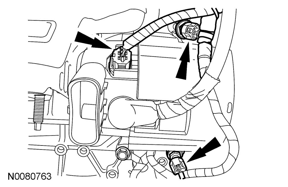
132. Connect the generator electrical connection and attach the 2 wiring harness retainers.

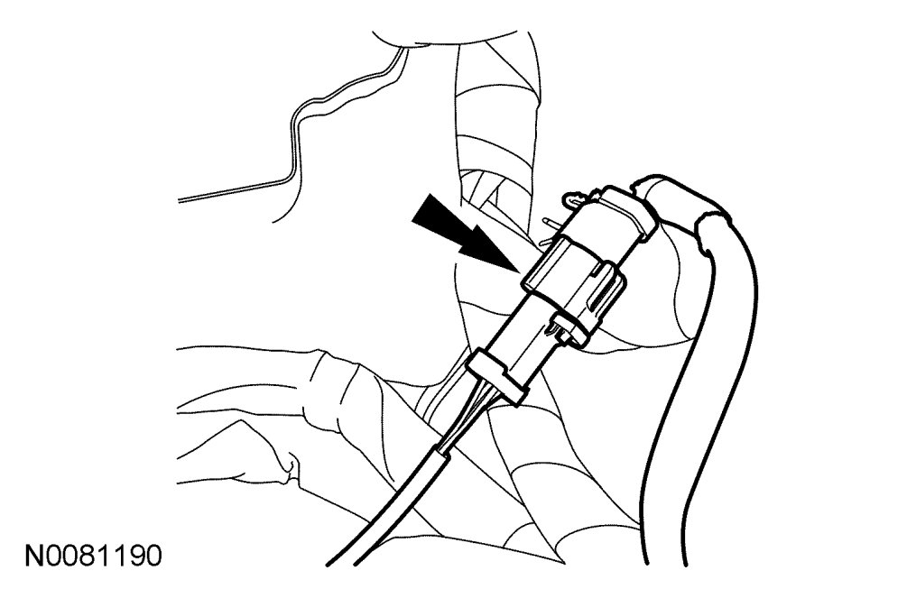
133. Connect the CKP sensor electrical connector.
- Attach the wiring harness-to-engine retainer.
134. Using the Heavy Duty Floor Crane and Spreader Bar, remove the engine from the engine stand.
Vehicles with automatic transaxles
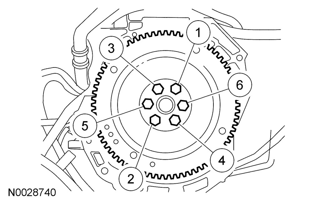
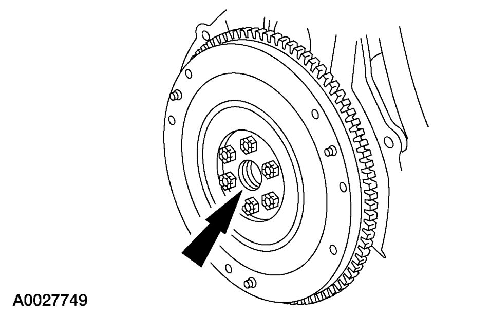
1. Install the flexplate and the bolts. Tighten the bolts in the sequence shown in 3 stages.
- Stage 1: Tighten to 50 Nm {5.1 kgf-m, 37 ft-lbf}.
- Stage 2: Tighten to 80 Nm {8.2 kgf-m, 59 ft-lbf}.
- Stage 3: Tighten to 112 Nm {11.4 kgf-m, 83 ft-lbf}.
Vehicles with manual transaxles

1. Install the flywheel and the bolts. Tighten the bolts in the sequence shown in 3 stages.
- Stage 1: Tighten to 50 Nm {5.1 kgf-m, 37 ft-lbf}.
- Stage 2: Tighten to 80 Nm {8.2 kgf-m, 59 ft-lbf}.
- Stage 3: Tighten to 112 Nm {11.4 kgf-m, 83 ft-lbf}.
2. Lubricate the transaxle input shaft pilot bearing with front axle grease.
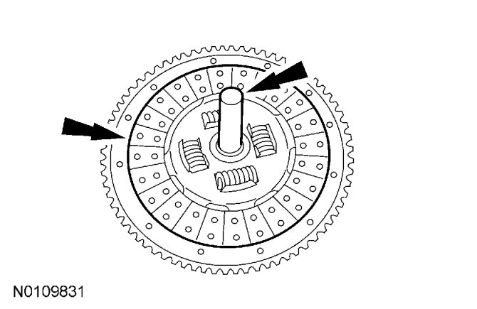
NOTE:Use a clutch disc aligner (such as OTC Clutch Alignment Tool Set 4528 or equivalent).
3. Using a suitable clutch disc aligner, position the clutch disc on the flywheel.
NOTE:If reusing the clutch pressure plate and flywheel, align the marks made during removal.
4. Position the clutch pressure plate and install the bolts.
- Tighten to 29 Nm {2.9 kgf-m, 21 ft-lbf} in a star pattern sequence.
NOTE:The Camshaft Alignment Plate is for camshaft alignment only. Using this tool to prevent engine rotation can result in engine damage.
62. Using the flats on the camshafts to prevent camshaft rotation, tighten the bolts.
- Tighten to 72 Nm {7.3 kgf-m, 53 ft-lbf}.
CAUTION:Do not use metal scrapers, wire brushes, power abrasive disks or other abrasive means to clean sealing surfaces. These tools cause scratches and gouges which make leak paths.
63. Clean and inspect the mounting surfaces of the engine and the front cover.

NOTE:The engine front cover must be installed and the bolts tightened within 4 minutes of applying the silicone gasket and sealant.
64. Apply a 2.5 mm (0.09 in) bead of silicone gasket and sealant to the cylinder head and oil pan joint areas. Apply a 2.5 mm (0.09 in) bead of silicone gasket and sealant to the front cover.

65. Install the engine front cover. Tighten the bolts in the sequence shown, to the following specifications:
- Tighten the 8-mm bolts to 10 Nm {1.0 kgf-m, 89 in-lbf}.
- Tighten the 13-mm bolts to 48 Nm {4.9 kgf-m, 35 ft-lbf}.

NOTE:Remove the through-bolt from the Camshaft Front Oil Seal Installer.
NOTE:Lubricate the oil seal with clean engine oil.
66. Using the Camshaft Front Oil Seal Installer, install a new crankshaft front oil seal.
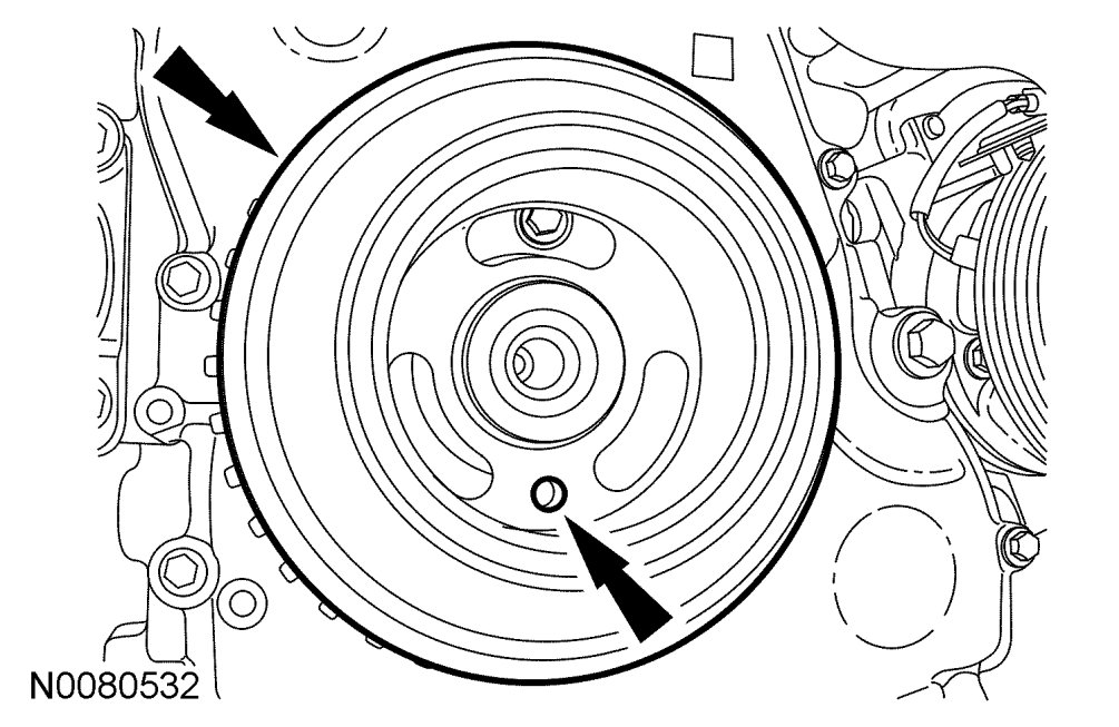
NOTE:Do not install the crankshaft pulley bolt at this time.
NOTE:Apply clean engine oil on the seal area before installing.
67. Position the crankshaft pulley onto the crankshaft with the hole in the pulley at the 6 o'clock position.
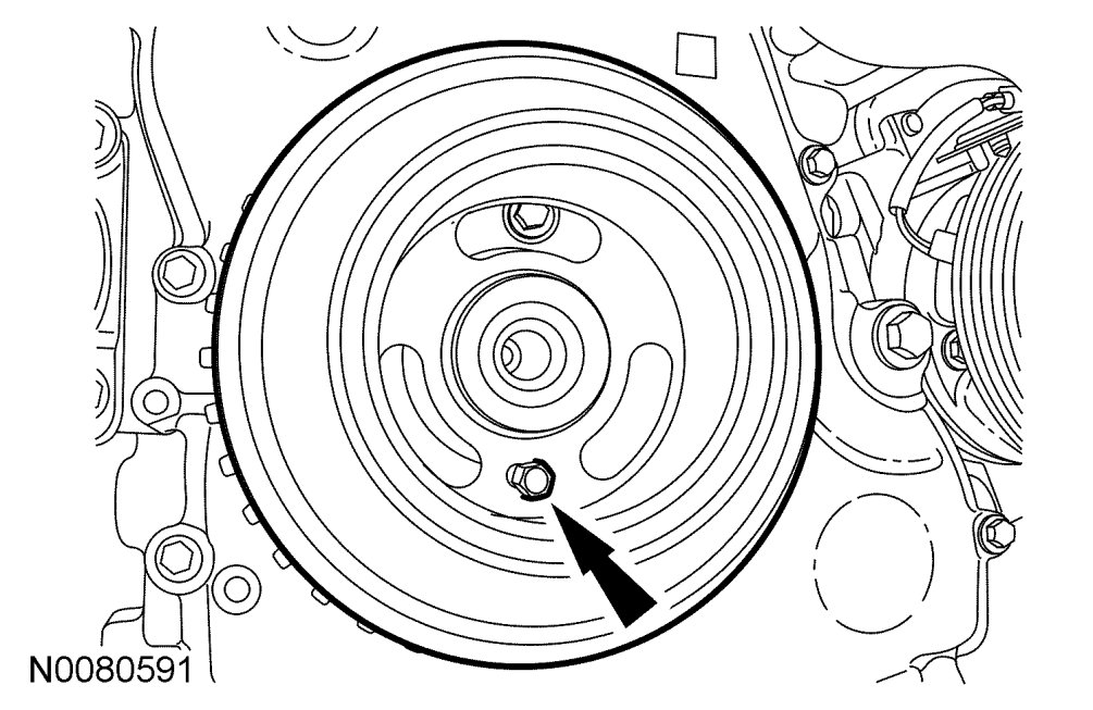
CAUTION:Only hand-tighten the 6 mm x 18 mm bolt or damage to the front cover can occur.
NOTE:This step will correctly align the crankshaft pulley to the crankshaft.
68. Install a 6 mm x 18 mm bolt through the crankshaft pulley and thread it into the front cover.

CAUTION:The crankshaft must remain in the Top Dead Center (TDC) position during installation of the pulley bolt or damage to the engine can occur. Therefore, the crankshaft pulley must be held in place with the Crankshaft Damper Holding Tool and the bolt should be installed using hand tools only.
NOTE:Do not reuse the crankshaft pulley bolt.
69. Install a new crankshaft pulley bolt. Using the Crankshaft Damper Holding Tool to hold the crankshaft pulley in place, tighten the crankshaft pulley bolt in 2 stages:
- Stage 1: Tighten to 100 Nm {10.2 kgf-m, 74 ft-lbf}.
- Stage 2: Tighten an additional 90 degrees (1/4 turn).
70. Remove the 6 mm x 18 mm bolt.
71. Remove the Crankshaft TDC Timing Peg.