 |
bwl1ge00000276
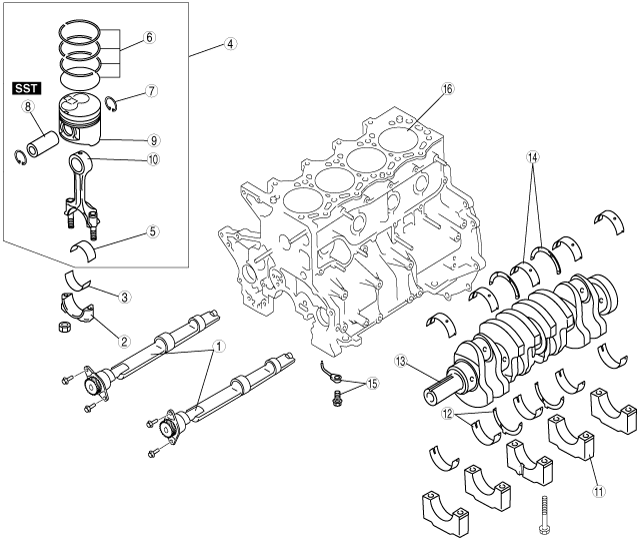
CYLINDER BLOCK DISASSEMBLY (III) [WLT-1, WLT-2, WL-3]
id011097500800
1. Disassemble in the order shown in the figure.
bwl1ge00000276
|
|
1
|
Balance shaft (If equipped)
|
|
2
|
Connecting rod cap
|
|
3
|
Lower connecting rod bearing
|
|
4
|
Piston, connecting rod
|
|
5
|
Upper connecting rod bearing
|
|
6
|
Piston ring
|
|
7
|
Piston pin clip
|
|
8
|
Piston pin
(See Piston Pin Disassembly Note .)
|
|
9
|
Piston
|
|
10
|
Connecting rod
|
|
11
|
Main bearing cap
|
|
12
|
Lower main bearing, lower thrust bearing
|
|
13
|
Crankshaft
(See Crankshaft Disassembly Note.)
|
|
14
|
Upper main bearing, upper thrust bearing
|
|
15
|
Oil jet valve, nozzle
|
|
16
|
cylinder block
|
Connecting Rod Cap Disassembly Note
1. Before removing the connecting rod cap, inspect the connecting rod side clearance. (See CONNECTING ROD INSPECTION [WLT-1, WLT-2, WL-3].)
Piston, Connecting Rod Disassembly Note
1. Before removing the piston and connecting rod, inspect the connecting rod oil clearance. (See CONNECTING ROD SIDE CLEARANCE INSPECTION [WLT-1, WLT-2, WL-3].)
2. Inspect the oscillation torque. (See PISTON AND CONNECTING ROD INSPECTION [WLT-1, WLT-2, WL-3].)
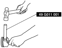
Piston Pin Disassembly Note
1. Remove the piston pin using the SST.
bwl1ge00000005
|
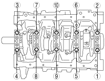
Main Bearing Cap Disassembly Note
1. Before removing the main bearing cap, inspect the crankshaft end play. (See CRANKSHAFT END PLAY INSPECTION/REPAIR [WLT-1, WLT-2, WL-3].)
2. Loosen the main bearing cap bolts in two or three steps in the order shown in the figure.
bwl1ge00000006
|
Crankshaft Disassembly Note
1. Before removing the crankshaft, inspect the main journal oil clearance. (See CRANKSHAFT OIL CLEARANCE INSPECTION/REPAIR [WLT-1, WLT-2, WL-3].)