BOOST SENSOR INSPECTION [WL-C, WE-C]
id0140b7809700
-
Note
-
• Perform the following inspection only when directed.
Visual Inspection
1. Inspect the boost sensor for damage and cracks.
-
• If there is any malfunction, replace the boost sensor/IAT sensor No.1.
• If there is not any malfunction, perform the “Voltage Inspection”.
Voltage Inspection
1. Turn the engine switch to the ON position (Engine off).
2. Set the M-MDS and monitor the MAP PID. (See ON-BOARD DIAGNOSTIC TEST [WL-C, WE-C (Thailand, General (L.H.D. R.H.D.) specs.)].) (See ON-BOARD DIAGNOSTIC TEST [WL-C, WE-C (Australian, European (L.H.D. U.K.) specs.)].)
-
• If not as specified, perform the “Circuit Open/Short Inspection”.
-
-
MAP PID (Reference)
-
Approx. 1.65 V [Atmospheric pressure 101 kPa {757.5 mmHg, 29.8 inHg}]
3. Start the engine and warm up the engine completely.
4. Monitor the MAP PID using the M-MDS at idle.
-
• If not as specified, perform the “Circuit Open/Short Inspection”.
-
-
MAP PID (Reference)
-
Approx. 1.65 V [Atmospheric pressure 101 kPa {757.5 mmHg, 29.8 inHg}]
Circuit Open/Short Inspection
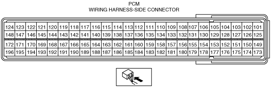
1. Disconnect the PCM connector. (See PCM REMOVAL/INSTALLATION [WL-C, WE-C].) (See PCM REMOVAL/INSTALLATION (U.K. Specs.) [WL-C, WE-C].)
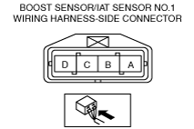
2. Disconnect the boost sensor/IAT sensor No.1 connector.
3. Inspect for open/short circuit in the following wiring harnesses.
-
• If there is open/short circuit, repair or replace wiring harnesses.
Open circuit
-
• Power circuit (Boost sensor/IAT sensor No.1 connector terminal D and PCM connector terminal 189)
• Signal circuit (Boost sensor/IAT sensor No.1 connector terminal C and PCM connector terminal 133)
• Ground circuit (Boost sensor/IAT sensor No.1 connector terminal A and PCM connector terminal 111)
Short circuit
-
• Boost sensor/IAT sensor No.1 connector terminal A and PCM connector terminal 111 short to power supply
• Boost sensor/IAT sensor No.1 connector terminal C and PCM connector terminal 133 short to power supply
• Boost sensor/IAT sensor No.1 connector terminal C and PCM connector terminal 133 short to body ground
• Boost sensor/IAT sensor No.1 connector terminal D and PCM connector terminal 189 short to power supply
• Boost sensor/IAT sensor No.1 connector terminal D and PCM connector terminal 189 short to body ground