 |
absggw00001082
WHEEL HUB, STEERING KNUCKLE REMOVAL/INSTALLATION [4X2 (HIGH CLEARANCE MODEL)]
id0311008004a4
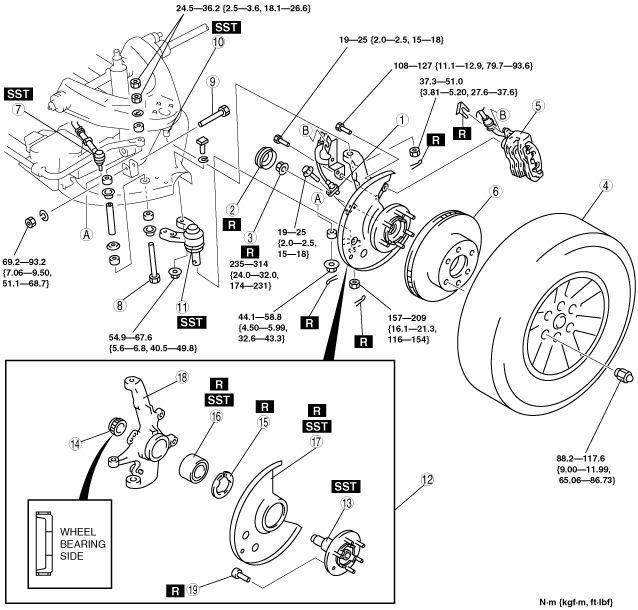
1. Remove in the order indicated in the table.
2. Install in the reverse order of removal.
absggw00001082
|
|
1
|
ABS wheel-speed sensor (with ABS)
|
|
2
|
Hub cap
|
|
3
|
Locknut
(See Locknut Removal Note)
|
|
4
|
Wheel and tire
|
|
5
|
Brake caliper component
|
|
6
|
Disc plate
|
|
7
|
Tie‐rod end ball joint
|
|
8
|
Bolt (stabilizer)
|
|
9
|
Bolt (shock absorber)
|
|
10
|
Upper arm ball joint
|
|
11
|
Lower arm ball joint
|
|
12
|
Wheel hub, steering knuckle, dust cover
|
|
13
|
Wheel hub component
|
|
14
|
ABS sensor rotor (with ABS) or spacer (without ABS)
|
|
15
|
Retaining ring
|
|
16
|
Wheel bearing
|
|
17
|
Dust cover
(See Dust Cover Removal Note)
|
|
18
|
Steering knuckle
|
|
19
|
Hub bolt
(See Hub Bolt Removal Note)
|
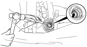
Locknut Removal Note
1. Knock the crimped portion of the locknut outward using a small chisel and a hammer.
absggw00001083
|
2. Remove the locknut.
absggw00001084
|
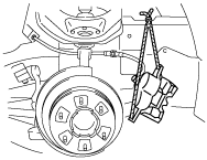
Brake Caliper Component Removal Note
1. Remove the brake caliper component, and suspend it with rope.
absggw00001085
|
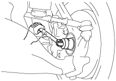
Tie-rod End Ball Joint Removal Note
1. Remove the tie rod-nut.
2. Separate the tie‐rod end from the steering knuckle using the SSTs.
absggw00001086
|
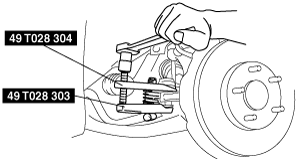
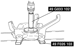
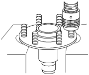
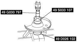
Wheel Hub Component Removal Note
1. Remove the wheel hub component using the SSTs and a press.
absggw00001087
|
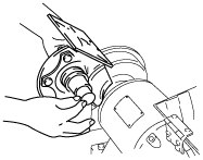
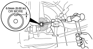
2. If the bearing inner race remains on the front wheel hub component, grind a section of the bearing inner race until approx. 0.5 mm {0.02 in} remains. Then remove it using a chisel.
absggw00001088
|
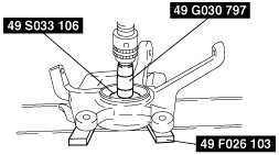
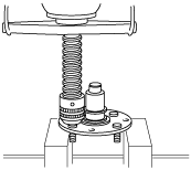
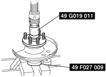
Wheel Bearing Removal Note
1. Remove the wheel bearing using the SSTs and a press.
absggw00001089
|
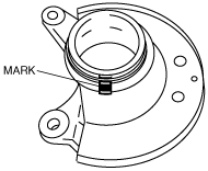
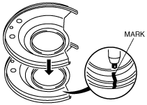
Dust Cover Removal Note
1. Mark the dust cover and steering knuckle for proper installation.
absggw00001090
|
2. Remove the dust cover using a chisel.
absggw00001091
|
Hub Bolt Removal Note
1. Remove the hub bolts using a press.
absggw00001092
|
Hub Bolt Installation Note
1. Install the new hub bolts using a press.
absggw00001093
|
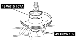
Dust Cover Installation Note
1. Mark the new dust cover in the same way as the removed one.
absggw00001094
|
2. Align the marks of the new dust cover and the knuckle.
3. Install the new dust cover using the SSTs and a press.
absggw00001095
|
Wheel Bearing Installation Note
1. Install the new wheel bearing using the SSTs and a press.
absggw00001096
|
Wheel Hub Component Installation Note
1. Install the wheel hub component using the SSTs and a press.
absggw00001097
|
Locknut Installation Note
1. Install a new locknut and stake it as shown.
absggw00001098
|