|
absggw00000841
STEERING GEAR AND LINKAGE REMOVAL/INSTALLATION
id061400800900
1. Remove the front ABS wheel-speed sensor. (with ABS) (See FRONT ABS WHEEL-SPEED SENSOR REMOVAL/INSTALLATION [4X2 (EXCEPT HIGH CLEARANCE MODEL)].) (See FRONT ABS WHEEL-SPEED SENSOR REMOVAL/INSTALLATION [4x2 (HIGH CLEARANCE MODEL), 4X4].)
2. Remove in the order indicated in the table.
3. Install in the reverse order of removal.
4. After installation, adjust the total toe-in. (See FRONT WHEEL ALIGNMENT [4x2].) (See FRONT WHEEL ALIGNMENT [4x4].)
absggw00000841
|
|
1
|
Cotter pin
|
|
2
|
Locknut
|
|
3
|
Ball joint
|
|
4
|
Tie rod
|
|
5
|
Locknut
|
|
6
|
Center link
|
|
7
|
Idler arm
|
|
8
|
Bushing
|
|
9
|
Washer
|
|
10
|
Bolt, Nut, washer
|
|
11
|
Idler arm bracket
|
|
12
|
Pressure pipe
|
|
13
|
Return pipe
|
|
14
|
Bolt
|
|
15
|
Bolt, Nut, Washer
|
|
16
|
Steering gear and pitman arm
|
|
17
|
Dust boot (Ball joint)
|
|
18
|
Dust boot (Idler arm)
|
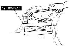
Ball Joint, Idler Arm, Steering Gear and Pitman Arm Removal Note
1. Remove the ball joint from the knuckle and center link, the idler arm from the center link, and steering gear and pitman arm from the center link using the SST.
absggw00000842
|
Dust Boot (Ball Joint), Dust Boot (Idler Arm) Removal Note
1. Place the chisel against the boot and hold it at the angle shown.
2. Remove the dust boot by tapping it with a hammer.
absggw00000843
|
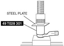
Dust Boot (Idler Arm) Installation Note
1. Wipe the grease off the ball joint.
2. Put a small amount of lithium-based grease into a new dust boot.
3. Install the dust boot using the SST and a press.
absggw00000844
|
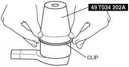
Dust Boot (Ball Joint) Installation Note
1. Wipe the grease off the ball joint.
2. Put a small amount of lithium-based grease into a new dust boot.
3. Install the dust boot onto to the ball joint.
4. Set the SST over the boot and install a new clip.
absggw00000845
|
5. Wipe away excessive grease.