1. Component views
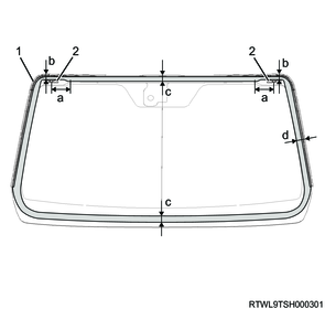
Front windshield glass
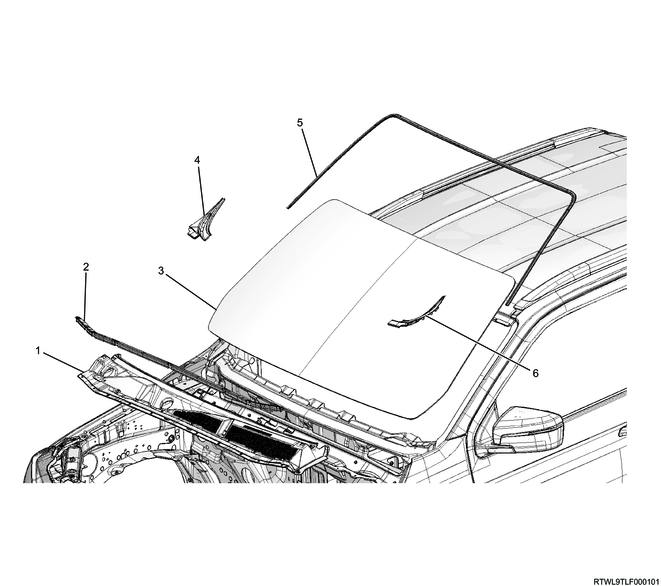
Part name
- Cowl cover
- Engine hood rear seal
- Front windshield glass
- Side cowl cover (RH)
- Molding
- Side cowl cover (LH)
2. Front windshield glass installation
1) Clean the front windshield glass using alcohol.
2) Clean the body panel using alcohol.
3) Apply primer to the body.
Note
- Apply Sunstar BP-901 or equivalent to the bonding surface of the body side.
- Primer application width: Top 29 mm {1.14 in}, Side 28 mm {1.10 in}, Bottom 30 mm {1.18 in}
4) Install the spacer and retainer to the body.
Caution
- Do not reuse the spacer.
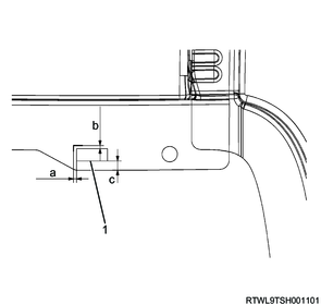
Legend
- Retainer
Dimensions
a: 0 to 2 mm { 0.00 to 0.08 in }
b: 0 to 2 mm { 0.00 to 0.08 in }
c: 6 mm { 0.24 in }
Legend
- Spacer
- Retainer
Dimensions
a. Primer application area: 29 mm {1.14 in}, top
b. Primer application area: 28 mm {1.10 in}, side
c. Primer application area: 30 mm {1.18 in}, bottom
5) Install the spacer to the front windshield glass.
Caution
- Do not reuse the spacer.
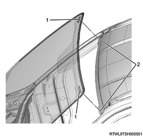
6) Install the molding to the front windshield glass.
Caution
- Do not reuse the molding.
Legend
- Molding
- Windshield support
- Spacer
- Spacer positioning mark
Dimensions
a. 40 mm {1.57 in}
7) Apply the primer to the front windshield glass.
Note
- Apply Sunstar GP-402 or equivalent to the bonding surface of the front windshield glass.
Legend
- Primer application area
- Windshield support
Dimensions
a. 100 mm {3.94 in}
b. 17 mm {0.67 in}
c. 25 mm {0.98 in}
d. 20.5 mm {0.81 in}
Note
- The primer application width should be 17 mm {0.67 in} to 25 mm {0.98 in} from the edge of the front windshield glass.
Caution
- After applying the primer, leave it for at least 1 minute for air drying.
8) Apply the sealing adhesive to the front windshield glass.

Legend
- Sealing agent
Dimensions
a. 11 mm {0.43 in}
b. 10 mm {0.39 in}
c. 2 mm {0.08 in}
d. 11 mm {0.43 in}
e. 25 mm {0.98 in} upper edge, 20.5 mm {0.81 in} lateral edge, 25 mm {0.98 in} lower edge
f. 44 mm {1.73 in}
g. 27 mm {1.06 in}
h. 28 mm {1.10 in}
i. 12 mm {0.47 in}
Caution
- If an air gun is used, use an air pressure that is less than or equal to the specified value.
Specified air pressure: 147 to 294 kPa {1.5 to 3.0 kgf/cm2 / 21 to 43 psi} or less
Note
- After the primer completely dries, apply sealing agent Sunstar penguinseal #560 or equivalent along the edge of the front windshield glass.
- The sealing agent should form a bonding area of 20 mm {0.79 in} at the lower right section of the front windshield glass.

Legend
- Molding
- Windshield support
- Spacer
- Sealing agent
Dimensions
a. 20 mm {0.79 in}
9) Install the front windshield glass to the body.
Caution
- Complete the bonding within 5 minutes of applying the sealing agent.
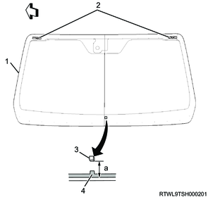
10) Insert the windshield support into the body panel mounting hole, and install the front windshield glass by pressing it into the panel.
Legend
- Windshield support
- Mounting hole
Note
- Wipe off the protruded sealing material with lead-free gasoline and a soft cloth.
3. Cowl cover installation
1) Install the cowl cover to the cowl panel.
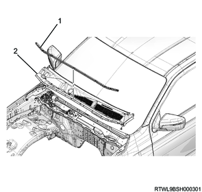
Legend
- Engine hood rear seal
- Cowl cover
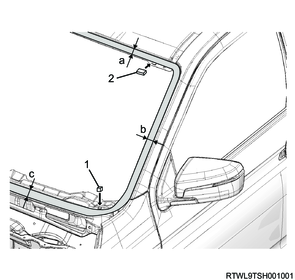
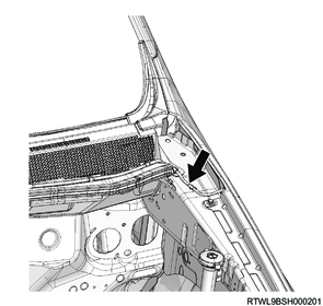
2) Connect the washer hose at the location shown in the following diagram.
3) Install the side cowl cover to the cowl cover.

Legend
- Side cowl cover
4. Wiper arm installation
1) Install to the vehicle so that the wiper blades comes to the positions away from the upper edge of the front window molding as shown in the diagram.
Tightening torque: 31 N・m { 3.2 kgf・m / 23 lb・ft }
Design blade type (RHD)
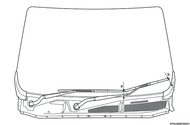
Standard value
a: 43.3 mm { 1.70 in }
b: 53.5 mm { 2.11 in }
Design blade type (LHD)
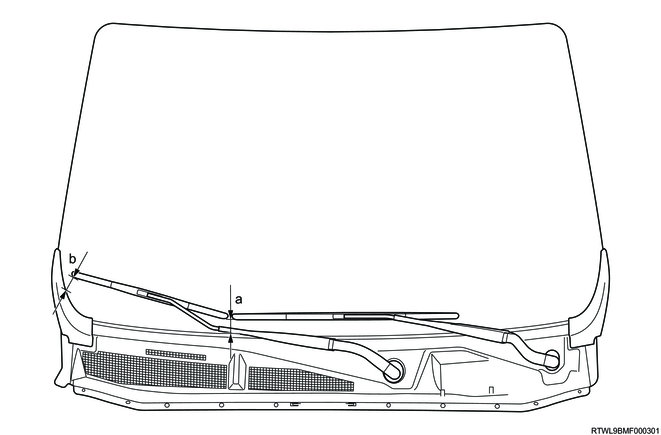
Standard value
a: 43.3 mm { 1.70 in }
b: 53.5 mm { 2.11 in }
Flat blade type (RHD)
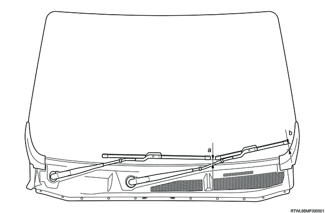
Standard value
a: 21.0 mm { 0.83 in }
b: 25.0 mm { 0.98 in }
Flat blade type (LHD)

Standard value
a: 21.0 mm { 0.83 in }
b: 25.0 mm { 0.98 in }
2) Install the wiper arm cover to the wiper arm.
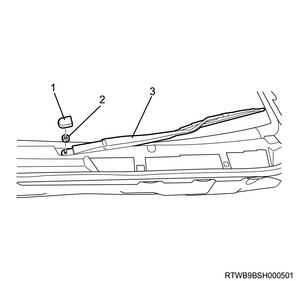
Legend
- Wiper arm cover
- Nut
- Wiper arm, blade
5. Rain and light sensor installation
1. Models with rain and light sensors
1) Clean the bonding surfaces of the rain and light sensor and front windshield glass using gasoline.
2) Install the rain and light sensor to the front windshield glass.
Caution
- Do not reuse the rain and light sensor
Legend
- Claw section
- Rain and light sensor
3) Connect the connector to the rain and light sensor.
4) Install the cover to the front windshield glass.
Legend
- Cover
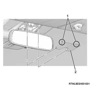
6. Room mirror installation
1. Models with automatic anti-glare mirrors (Models with stereo cameras)
1) Connect the connector to the room mirror.
2) Install the room mirror to the front windshield glass.
Tightening torque: 1.2 N・m { 0.12 kgf・m / 10.6 lb・in }
Legend
- Room mirror
- Screw
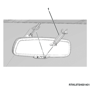
2. Models with manual anti-glare mirrors (Models with stereo cameras)
1) Install the room mirror to the front windshield glass.
Tightening torque: 1.2 N・m { 0.12 kgf・m / 10.6 lb・in }

Legend
- Room mirror
- Screw
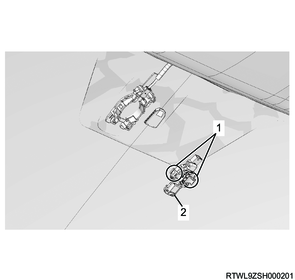
3. Models with automatic anti-glare mirrors (Models without stereo cameras)
1) Connect the connector to the room mirror.
2) Install the room mirror to the front windshield glass.
Tightening torque: 1.2 N・m { 0.12 kgf・m / 10.6 lb・in }

Legend
- Room mirror
- Screw
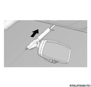
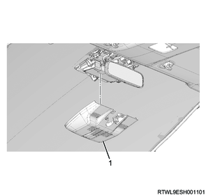
3) Install the harness cover to the front windshield glass.
Legend
- Harness cover
4) Pull up the upper part of the harness cover in the direction of the arrow until it comes contact with the head lining.
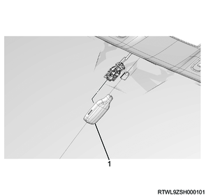
4. Models with manual anti-glare mirrors (Models without stereo cameras)
1) Install the room mirror to the front windshield glass.
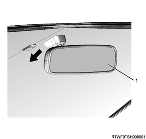
Legend
- Room mirror
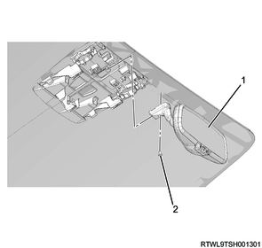
5. Models without anti-glare mirrors
1) Install the room mirror to the front windshield glass.
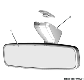
Legend
- Room mirror
- Mirror base
7. Stereo camera installation
1. Models with stereo cameras
Caution
- Perform work without touching the stereo camera lens.
- If the stereo camera lens is touched, replace the stereo camera.
- Do not subject the stereo camera to a strong impact.
1) Clean the inside of the stereo camera bracket opening using air.
Legend
- Stereo camera bracket opening
2) When installing a new stereo camera, remove the lens cap from the stereo camera.
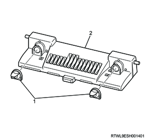
Legend
- Lens cap
- Stereo camera
3) Install the stereo camera to the stereo camera bracket.
Caution
- Do not press the aluminum tape section.
Legend
- Aluminum tape
- Stereo camera
4) Connect the connector to the stereo camera.
5) Install the stereo camera cover to the front windshield glass.
Legend
- Stereo camera cover
6) Slide the stereo camera cover in the direction of the arrow.
Caution
- Make sure that the claw section is locked.
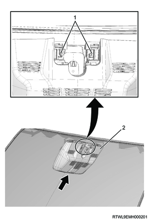
Legend
- Claw section
- Stereo camera cover
7) Install the stereo camera cover lid to the stereo camera cover.
Legend
- Claw section
- Stereo camera cover lid
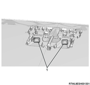
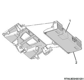
8. Instrument panel installation
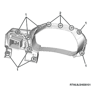
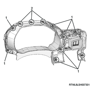
1) Install the instrument panel (upper side) to the instrument panel (lower side).
Tightening torque: 2.5 N・m { 0.25 kgf・m / 22.1 lb・in }
High grade type
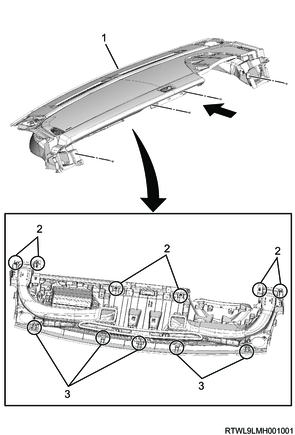
Legend
- Instrument panel (Upper side)
- Clip
- Claw section
Low grade type
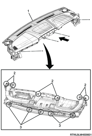
Legend
- Instrument panel (Upper side)
- Clip
- Claw section
2) Connect the connector to the instrument panel (upper side).
3) Connect the passenger airbag to the reinforcement.
Tightening torque: 25 N・m { 2.5 kgf・m / 18 lb・ft }
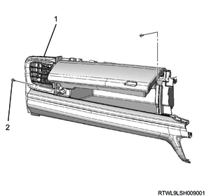
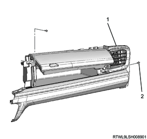
4) Install the side cover to the instrument panel.
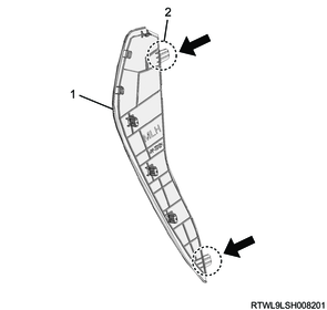
Legend
- Side cover
- Claw section
9. Meter cluster installation
1) Install the meter cluster to the instrument panel.
RHD
Legend
- Clip
- Claw section
LHD
Legend
- Clip
- Claw section
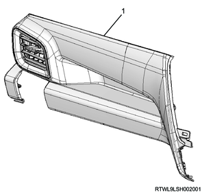
10. Instrument panel passenger-side upper cover installation
1) Install the instrument panel passenger-side upper cover to the instrument panel.
Tightening torque: 2.5 N・m { 0.25 kgf・m / 22.1 lb・in } High grade type
High grade type (RHD)
Legend
- Instrument panel passenger-side upper cover
- Screw
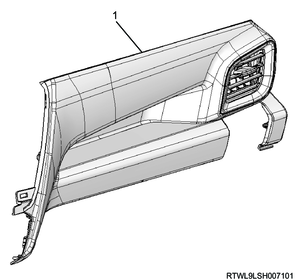
High grade type (LHD)
Legend
- Instrument panel passenger-side upper cover
- Screw
Low grade type (RHD)
Legend
- Instrument panel passenger-side upper cover
Low grade type (LHD)
Legend
- Instrument panel passenger-side upper cover
11. Audio and navigation system installation
1. Models equipped with display units
1) Connect the connector to the display unit.
2) Install the display unit as a set with the bezel to the instrument panel.
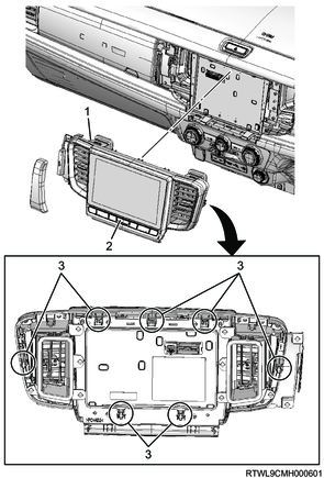
Legend
- Bezel
- Display unit
- Clip
2. Models equipped with 2DIN audio
1) Connect the connector to the 2DIN audio.
2) Install the 2DIN audio as a set with the bezel to the instrument panel.
Note
- Align the pin position with the bracket to install.
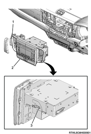
Legend
- Bezel
- 2DIN audio
- Pin
12. Head lining installation
Refer to "9.Body, Cab, Accessories 9L.Exterior, Interior Trim head lining (regular cab) installation".
Refer to "9.Body, Cab, Accessories 9L.Exterior, Interior Trim head lining (crew cab) installation".
Refer to "9.Body, Cab, Accessories 9L.Exterior, Interior Trim head lining (extended cab) installation".
13. SRS airbag setting
1. SRS reactivation
Warning
- Never use SRS parts from other vehicles or models.
- Make sure to check the part numbers and use the SRS components intended for the target vehicle.
1) Set the ignition switch to LOCK and remove the key.
Note
- For models with the passive entry and start system, turn the power mode OFF.
2) Make sure that the connectors of the SRS components (SRS airbag, SRS control unit, seat belt with pretensioner, SRS coil, etc.) are fully connected.
3) Install the SRS fuse to the fuse relay box, and connect the battery cable to the negative terminal of the battery.
4) Turn ON the ignition switch and verify that the SRS airbag warning light turns OFF after illuminating for 6 seconds.
Caution
- If the SRS airbag warning light does not operate properly, perform Diagnostic system check - SRS controls.
5) Referring to the following, perform the setting of the front door power window switch with AUTO UP/AUTO DOWN function.
Refer to "9.Body, Cab, Accessories 9T.Glass, Windows, Mirrors front door power window switch setting".
14. Stereo camera setting
1. Stereo camera learned value clearing
Note
- Perform only when stereo camera relearning is performed.
1) Connect the scan tool to the DLC.
2) Turn ON the ignition switch.
3) Select Special Function on the scan tool.
- Diagnostics > Body > Stereo Camera > Special Function
4) Select Camera Aiming Clear, and follow the on-screen instructions to clear the learned value.