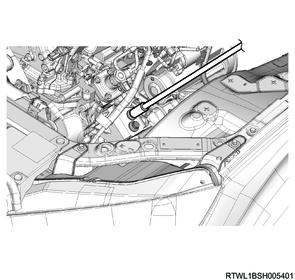
1. Engine installation
1) Install the engine to the vehicle using a hoist.
Note
- Slowly operate to move the engine to the installation position.
- Slowly operate the hoist so that the transmission side is low, while pulling to the rear of the engine.
2) Connect the engine mounting to the engine foot.
Caution
- Always tighten bolts while the engine is securely seated on the frame to prevent bolts from loosening.
Tightening torque: 131 N・m { 13.4 kgf・m / 97 lb・ft }
Engine left side
Engine right side
3) Remove the wire from the engine hanger and hoist.
4) Remove special tool from the cylinder head.
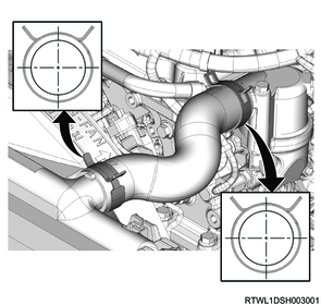
2. Radiator lower hose connect
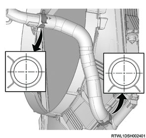
1) Connect the radiator lower hose and clamp to the water intake pipe.
Note
- Insert the lower hose until it makes full contact with the pipe.
- Soapy water can be applied when installing the lower hose.
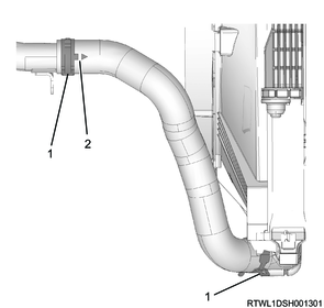
Legend
- Clamp
- Arrow mark
Note
- Align the clamp with the lower hose arrow mark end to install.
Legend
- Clamp
- Arrow mark
- Radiator lower hose
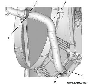
Note
- Install the clamp in the direction shown in the following diagram.
- The diagram about the clamp direction shows the state viewed from the vehicle front.
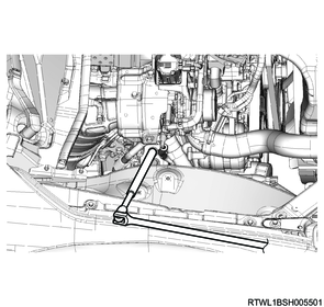
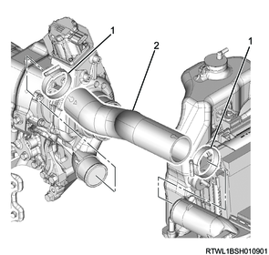
3. Power steering oil pump connect
1) Install the power steering oil pump to the timing gear case.
Tightening torque: 25 N・m { 2.5 kgf・m / 18 lb・ft }
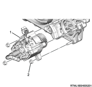
Legend
- Power steering oil pump
- Nut
2) Install the power steering oil hose to the bracket.
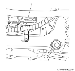
Legend
- Bracket
4. Fuel hose connect
1) Connect the fuel return hose to the fuel leak-off pipe.
2) Connect the fuel feed hose to the fuel supply pump.
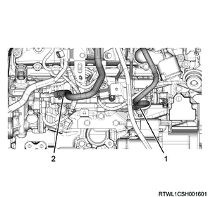
Legend
- Fuel return hose
- Fuel feed hose
5. Vacuum hose connect
1) Connect the vacuum hose to the vacuum pipe.
6. ECM connect
1) Connect the harness to the frame.
2) Pull in the harness toward inside the room.
3) Connect the connector to the ECM.
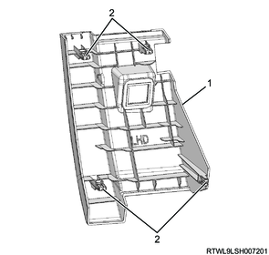
7. Instrument panel passenger-side lower cover installation
1) Connect the connector to the instrument panel passenger-side lower cover.
2) Install the instrument panel passenger-side lower cover to the instrument panel.
RHD

Legend
- Instrument panel passenger-side lower cover
- Clip
LHD
Legend
- Instrument panel passenger-side lower cover
- Clip
8. Glove box installation
1) Install the glove box to the instrument panel.
RHD
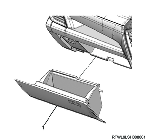
Legend
- Glove box
LHD
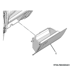
Legend
- Glove box
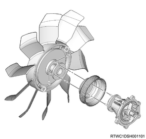
9. Cooling fan installation
1) Install the fan pulley to the water pump.
2) Install the cooling fan and cooling fan clutch as a set to the water pump.
Tightening torque: 10.0 N・m { 1.0 kgf・m / 89 lb・in }
10. Cooling fan belt installation
1) Install the cooling fan belt to the following parts.
- Fan pulley
- Generator
- Crankshaft pulley
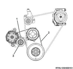
Legend
- Adjust bolt
- Cooling fan belt
- Lock nut
11. Fan guide installation
1) Install the fan guide to the radiator.
Tightening torque: 6.5 N・m { 0.7 kgf・m / 58 lb・in }
2) Install the fan shroud to the fan guide.
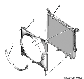
Legend
- Fan shroud
- Fan guide
- Radiator
12. A/C compressor connect
1) Connect the A/C compressor to the A/C compressor bracket.
Tightening torque: 51 N・m { 5.2 kgf・m / 38 lb・ft }
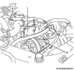
Legend
- A/C compressor bracket
- A/C compressor
13. A/C compressor drive belt installation
1) Install the A/C compressor drive belt to the following parts.
- Tension pulley
- A/C compressor
- Crankshaft pulley
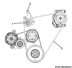
Legend
- Lock nut
- Adjust bolt
- A/C compressor drive belt
14. Radiator reserve tank installation
1) Clean the radiator reserve tank using detergent.
Note
- Wash with clean water, and drain the water.
2) Assemble the reserve tank hose to the radiator reserve tank.
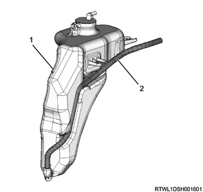
Legend
- Radiator reserve tank
- Reserve tank hose
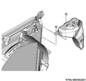
3) Install the radiator reserve tank to the fan guide.
Tightening torque: 8.4 N・m { 0.9 kgf・m / 74 lb・in }
4) Connect the radiator reserve tank hose to the radiator.
Caution
- Assemble the reserve tank hose to the dent to fit the radiator reserve tank shape.
15. Radiator upper hose installation
1) Install the radiator upper hose and clamp to the thermostat and radiator.
Note
- Align the painted arrow on the upper hose with the pipe boss section to install.
- Insert the upper hose until it makes full contact with the pipe.
- Soapy water can be applied when installing the upper hose.
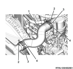
Legend
- Radiator upper hose
- Boss section
- Clamp
- Arrow mark
Note
- Align the clamp with the upper hose arrow mark end to install.
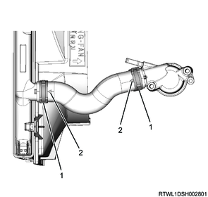
Legend
- Clamp
- Arrow mark
Note
- Install the clamp in the direction shown in the following diagram.
- The diagram about the clamp direction shows the state viewed from the vehicle front.
16. Oil level gauge guide tube installation
1) Apply engine oil to the O-ring.
Caution
- Do not reuse the O-ring.
2) Install the oil level gauge guide tube to the crankcase.
Tightening torque: 25 N・m { 2.5 kgf・m / 18 lb・ft }

3) Install the oil level gauge to the oil level gauge guide tube.
17. Fuse box connect
1) Connect the battery harness to the fuse box.
2) Connect the engine harness to the fuse box.
3) Install the fuse box cover to the fuse box.
18. Clutch installation
19. Transmission installation
20. Battery installation
1) Install the battery to vehicle.
2) Install the battery bracket to the frame.
Tightening torque: 4.0 N・m { 0.41 kgf・m / 35.4 lb・in } Battery side
Tightening torque: 20 N・m { 2.0 kgf・m / 15 lb・ft } Frame side
3) Connect the battery cable to the battery.
4) Connect the battery ground cable to the frame.
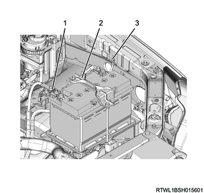
Legend
- Battery cable
- Battery bracket
- Battery ground cable
21. Air cleaner installation
1) Install the air cleaner to the vehicle.
Tightening torque: 20 N・m { 2.0 kgf・m / 15 lb・ft }
2) Connect the connector to the MAF and IAT sensor.
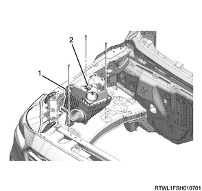
Legend
- Air cleaner
- MAF and IAT sensor
22. Air intake hose installation
1) Install the air intake hose to the intake throttle valve and intercooler.
Caution
- Align the marks on the pipe side and hose side.
Tightening torque: 5.0 N・m { 0.5 kgf・m / 44 lb・in }

Legend
- Air intake hose
- Clamp
23. Intake hose installation
1) Install the intake hose to the intercooler and turbocharger.
Caution
- Align the marks on the pipe side and hose side.
Tightening torque: 5.0 N・m { 0.5 kgf・m / 44 lb・in }
Legend
- Clamp
- Intake hose
24. Air duct installation
1) Align the air duct with the air cleaner and turbocharger.
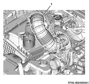
Legend
- Air duct
2) Referring to the diagram, align the alignment mark positions and connect the air duct to the turbocharger.
Tightening torque: 4.0 N・m { 0.4 kgf・m / 35 lb・in }
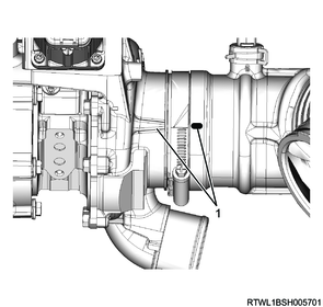
Legend
- Alignment mark
3) Install the PCV hose to the cylinder head cover and air duct.
Caution
- Align the marks on the pipe side and hose side.
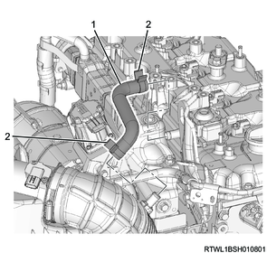
Legend
- PCV hose
- Clamp
4) Install the intake air duct to the air cleaner and radiator core support.
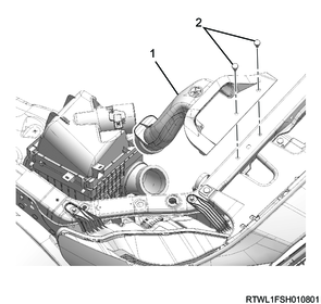
Legend
- Intake air duct
- Clip
25. Exhaust pipe installation
26. Underguard installation
27. Preliminary and post procedures
1. Post procedures
1) Lower the vehicle.
2) Connect the battery cable to the battery negative terminal.
3) Referring to the following, perform the setting of the front door power window switch with AUTO UP/AUTO DOWN function.
Refer to "9.Body, Cab, Accessories 9T.Glass, Windows, Mirrors front door power window switch setting".
4) Close the engine hood.
28. Fuel air bleed
1) Open the engine hood.
2) Press the priming pump until it becomes hard.
Caution
- Completely bleed air, as insufficient air bleeding may lead to engine malfunctions.
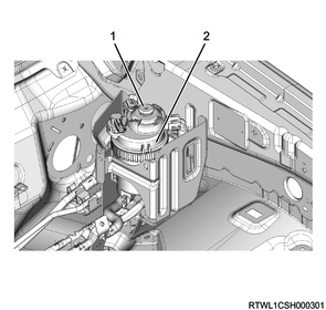
Legend
- Priming pump
- Fuel filter with sedimenter
29. Coolant filling
1) Fill with engine coolant up to the radiator filler neck.
Note
- Fill with engine coolant of the specified concentration to the brim of the radiator cap inlet.
Caution
- Fill slowly to prevent air from entering the system.
2) While pressing the radiator upper hose manually several times to bleed the air from the hose, fill the radiator with engine coolant.
Note
- Fill with engine coolant up to the brim of the radiator cap inlet with the amount the engine coolant lowers.
Caution
- Repeat the operation until the coolant level no longer drops.
3) Add engine coolant up to the MAX line of the radiator reserve tank.
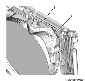
Legend
- Radiator reserve tank
- MAX line
- MIN line
4) Install the radiator cap to the radiator.
5) Start and idle the engine.
Caution
- Idle the engine for 5 minutes or more.
6) Stop the engine.
7) Remove the radiator cap from the radiator.
Warning
- Do not loosen the radiator cap or reserve tank cap when coolant is hot, as doing so may result in burns caused by the release of steam or hot water.
- When opening the radiator cap, cover the cap with a thick cloth once the engine coolant has cooled and slowly turn to release pressure.
8) Fill with engine coolant up to the radiator filler neck.
Note
- If the engine coolant is excessively low, inspect for engine coolant leakage from the cooling system.
9) Install the radiator cap to the radiator.
10) Start the engine.
11) Increase the engine speed to around 2000 rpm and run the engine for 10 minutes once the engine coolant temperature gauge reaches the center.
12) With the engine running, check that the thermostat valve is open.
Note
- Touch the radiator upper hose, and confirm that it has become warm.
- If it has not become warm, go back to Step 11.
Caution
- Do not try determining it by using only an engine coolant temperature gauge.
13) Idle the engine for 5 minutes.
14) Stop the engine.
15) Remove the radiator cap from the radiator.
Warning
- Do not loosen the radiator cap or reserve tank cap when coolant is hot, as doing so may result in burns caused by the release of steam or hot water.
- When opening the radiator cap, cover the cap with a thick cloth once the engine coolant has cooled and slowly turn to release pressure.
16) Fill with engine coolant up to the radiator filler neck.
Note
- Fill with engine coolant of the specified concentration to the brim of the radiator cap inlet.
17) Add engine coolant up to the MAX line of the radiator reserve tank.
18) Install the radiator cap to the radiator.
19) Repeat steps 10 to 18 until the coolant level no longer lowers.
Caution
- If the level of the radiator reserve tank has fallen the next morning, add up to the MAX line.
30. Cooling fan belt adjustment
When installing a new belt, initial stretching of the belt occurs.
In addition, when reusing the belt, the belt needs to be fitted to the pulley groove.
After fitting the cooling fan belt, readjust the cooling fan belt tension.
1) Loosen the tension pulley lock nut using a wrench.
2) Adjust the cooling fan belt tension by turning the adjust bolt.
Note
- The standard amount of deflection shown is the value obtained when the standard pressure is applied to the midpoint of the fan pulley and generator.
Standard: 98 N { 10.0 kg / 22 lb }
Caution
- Accurately adjust the tension as there is a possibility the service life of the belt may be shortened or belt squeal may be generated if the tension is not within the appropriate range.
- Use a sonic tension meter to verify accurate tension adjustment.
| Adjustment conditions |
Deflection |
Vibration frequency |
| When new |
5.0 to 6.0 mm { 0.20 to 0.24 in } |
207 to 231 Hz |
| Reused |
7.0 to 7.8 mm { 0.28 to 0.31 in } |
176 to 190 Hz |
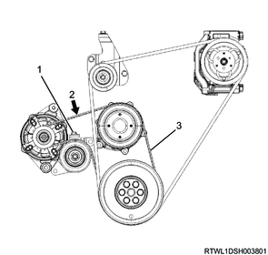
Legend
- Tension pulley adjust bolt
- Measurement point
- Cooling fan belt
3) Tighten the tension pulley lock nut to the specified torque.
Tightening torque: 41 N・m { 4.2 kgf・m / 30 lb・ft }
31. A/C compressor drive belt adjustment
When installing a new belt, initial stretching of the belt occurs.
In addition, when reusing the belt, the belt needs to be fitted to the pulley groove.
After fitting the A/C compressor drive belt, adjust the tension of the A/C compressor drive belt again.
1) Loosen the tension pulley lock nut.
2) Turn the tension pulley adjust bolt to adjust the tension.
Note
- The standard deflection shown is the value obtained when the specified load is applied to the measurement point of the A/C compressor drive belt.
98 N { 10.0 kg / 22 lb } Load
Caution
- Accurately adjust the tension as there is a possibility the service life of the belt may be shortened or belt squeal may be generated if the tension is not within the appropriate range.
- Use a sonic tension meter to verify accurate tension adjustment.
| Adjustment conditions |
Deflection |
Vibration frequency |
| When new |
12.5 to 16.5 mm { 0.49 to 0.65 in } |
92 to 112 Hz |
| Reused |
16.5 to 19.1 mm { 0.65 to 0.75 in } |
79 to 91 Hz |
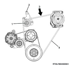
Legend
- Lock nut
- Adjust bolt
- Measurement point
- A/C compressor drive belt
3) Tighten the tension pulley lock nut to the specified torque.
Tightening torque: 51 N・m { 5.2 kgf・m / 38 lb・ft }
32. ECM setting
If the engine is replaced, perform Injector ID Code programming and ECM learned value clear.
1. Injector ID Code programming
Check the label attached to the engine cover at the time of factory shipment or the housing of each injector for the Injector ID Code.
Label on the cylinder head cover (Sample)
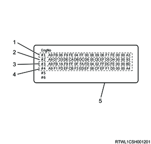
Legend
- No. 1 cylinder Injector ID Code
- No. 2 cylinder Injector ID Code
- No. 3 cylinder Injector ID Code
- No. 4 cylinder Injector ID Code
- Injector ID Code label
The correct order of the ID codes shown in the following injector illustration is as follows.
A9 D7 D3 DE CA DB DC D8 U5 CE EF D5 D4 00 00 93
Injector (Sample)
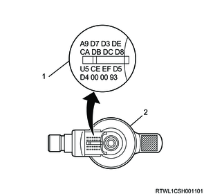
Legend
- Injector ID Code
- Injector
1) Connect the scan tool to the DLC.
2) Turn ON the ignition switch.
3) Select the scan tool item.
- Diagnostics > Engine > 4JJ3 > Programming > Injector ID Code > Program Injector ID Code
4) Program the Injector ID Code into the ECM by following the on-screen instructions.
5) After the programming is completed, turn the ignition switch OFF for 30 seconds.
33. Engine vehicle inspection
1. Inspection before starting the engine
1) Inspect for the following.
- Engine oil level
- Engine coolant level
- Items around the engine that may get caught
2. Inspection after starting the engine
1) Inspect for the following.
- Abnormal noise
- Abnormal vibration
- Fuel leakage
- Oil leakage
- Water leakage
- Air leakage
- Exhaust gas leakage
- Exhaust gas color
3. Inspection after stopping the engine
1) Inspect for the following.
- Engine oil level
- Engine coolant level