1. DTC P0016 description
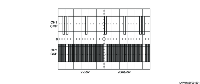
The CKP sensor is installed on the top of the flywheel housing. There are 56 notches spaced 6° apart and a 30° opening on the outer circumference of the flywheel. Top dead center of cylinder No. 1 can be detected through this opening. The CMP sensor is installed to the left side of the rear of the cylinder head. The sensor rotor is fixed on the inlet camshaft gear. The sensor rotor has 4 projections evenly spaced 90° apart and 1 reference projection. The CMP sensor detects 5 projections in total per 1 engine cycle. From the CKP sensor signal and CMP sensor signal, the ECM determines compression top dead center of cylinder No. 1 to make sure they correlate with each other. If the ECM detects that both signals are not synchronized, the DTC is set.
Each sensor signal waveform (When idling)
2. Condition for setting DTC P0016
Condition for running the DTC
- The battery voltage is 9 to 16 V.
- The ignition voltage is 9 to 16 V.
- The ignition switch is ON.
- The CKP sensor signal pulses are detected.
- The CMP sensor signal pulses are detected.
- DTCs P0335, P0336, and P0340 are not set.
Refer to "51.Engine Control 1A.Troubleshooting(RZ4E-TC) DTC P0335 (Flash Code 15) Crankshaft Position Sensor Circuit".
Refer to "51.Engine Control 1A.Troubleshooting(RZ4E-TC) DTC P0340 (Flash Code 14) Camshaft Position Sensor Circuit".
Condition for setting the DTC
- The ECM detects that the CKP sensor signal and the CMP sensor signal are not synchronized while the engine is running.
3. Action taken when DTC P0016 sets
- Euro4: The ECM illuminates the MIL. Refer to Action taken when DTC sets - Type A (Euro4).
- Except Euro4: The ECM illuminates the check engine warning light. Refer to Action taken when DTC sets - Type A (Except Euro4).
Refer to "51.Engine Control 1A.Troubleshooting(RZ4E-TC) DTC type definitions".
- The ECM inhibits engine startup.
4. Condition for clearing DTC P0016
- Euro4: Refer to Condition for clearing the MIL/DTC - Type A or Type B (Euro4).
- Except Euro4: Refer to Condition for clearing the check engine warning light/DTC - Type A or Type B (Except Euro4).
Refer to "51.Engine Control 1A.Troubleshooting(RZ4E-TC) DTC type definitions".