 |
ac5jjw00002355
ANTENNA FEEDER NO.3 REMOVAL/INSTALLATION
id092000812900
1. Disconnect the negative battery cable. (See NEGATIVE BATTERY CABLE DISCONNECTION/CONNECTION [SKYACTIV-G 2.0, SKYACTIV-G 2.5].) (See NEGATIVE BATTERY CABLE DISCONNECTION/CONNECTION [SKYACTIV-G 2.0, SKYACTIV-G 2.5 (WITHOUT i-stop)].) (See NEGATIVE BATTERY CABLE DISCONNECTION/CONNECTION [SKYACTIV-D 2.2].)
2. Remove the following parts:
3. Remove the rear passenger's assist handle. (See ASSIST HANDLE REMOVAL/INSTALLATION.)
4. Partially peel back the headliner.
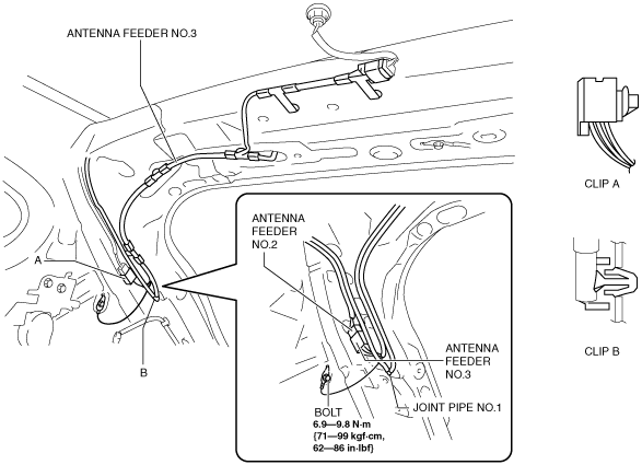
5. Disconnect antenna feeder No.2.
ac5jjw00002355
|
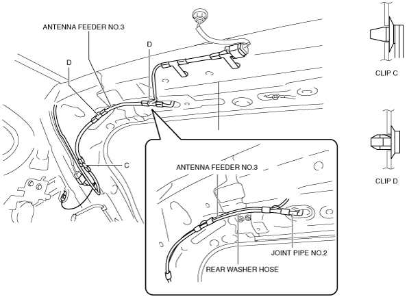
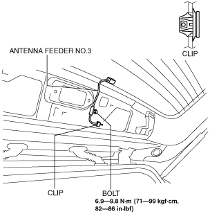
6. Remove the bolt.
7. Detach clip A.
8. Remove the joint pipe No.1 clip B.
9. Remove clips C and D.
ac5jjw00002356
|
10. Disconnect joint pipe No.2.
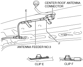
11. Remove clips E and F.
ac5jjw00002357
|
12. Disconnect the center roof antenna.
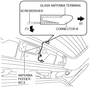
13. Using a screwdriver wrapped in protective tape, pull the connector in the direction of the arrow (2) shown in the figure while pressing glass antenna terminal in the direction of the arrow (1) shown in the figure, and disengage the glass antenna terminal from the connector. (with RDS (radio data system))
ac5jjw00002337
|
14. Disconnect the connector. (with RDS (radio data system))
15. Remove the bolts. (with RDS (radio data system))
ac5wzw00003770
|
16. Remove the clip. (with RDS (radio data system))
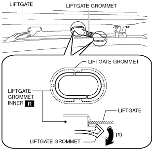
17. Partially peel the liftgate grommet in the direction of arrow (1) shown in the figure, and remove the liftgate grommet from the liftgate grommet inner. (with RDS (radio data system))
ac5jjw00001165
|
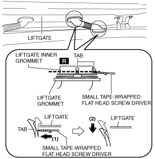
18. Using a screwdriver wrapped in protective tape, pull the liftgate grommet in the direction of the arrow (2) shown in the figure while pressing the liftgate grommet inner tab in the direction of the arrow (1) shown in the figure, and disengage the liftgate from the liftgate grommet. (with RDS (radio data system))
ac5wzw00005340
|
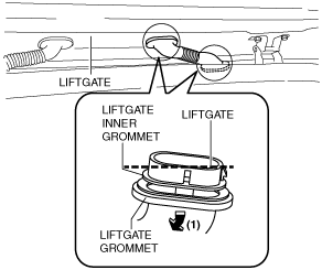
19. Pull the liftgate grommet in the direction of the arrow (1) shown in the figure and remove it.
ac5jjw00002358
|
20. Pull out the disconnected connectors on the liftgate side and vehicle interior side and antenna feeder No.3. (with RDS (radio data system))
21. Remove antenna feeder No.3.
22. Install in the reverse order of removal.