 |
ac5uuw00009763
DTC P2200:00 [DOSING CONTROL UNIT (SKYACTIV-D 2.2)]
id0102k1725700
Details On DTCs
|
DESCRIPTION |
NOx sensor No.1 control circuit range/performance problem |
|
|---|---|---|
|
DETECTION CONDITION
|
Determination conditions
|
• Any one of the following conditions is met:
|
|
Preconditions
|
• Battery voltage: 10.9—16 V
• CAN communication is normal at engine start for a continuous 20 s or more
• The following DTCs is not detected:
|
|
|
Drive cycle
|
• 1
|
|
|
Self test type
|
• CMDTC self test
|
|
|
Sensor used
|
• NOx sensor No.1
• Dosing control unit
|
|
|
FAIL-SAFE FUNCTION
|
• Restricts the maximum remaining distance to empty.
• Limits the upper limit of the engine speed.
|
|
|
VEHICLE STATUS WHEN DTCs ARE OUTPUT
|
• DTC P2BAF:00 is also stored in the PCM and the vehicle speed is restricted.
• DTC P1640:00 is also stored in the PCM.
• P0615:00 may be stored if the remaining distance to empty is 0 km {0 mile} and the engine cannot be restarted.
|
|
|
POSSIBLE CAUSE
|
• NOx sensor No.1 connector or terminals malfunction
• Dosing control unit connector or terminals malfunction
• NOx sensor No.1 loose
• Open or short circuit in wiring harness between the following terminals:
• NOx sensor No.1 malfunction
• Dosing control unit malfunction
|
|
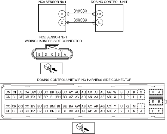
System Wiring Diagram
ac5uuw00009763
|
Function Explanation (DTC Detection Outline)
Repeatability Verification Procedure
1. Perform the "COMPULSORY DIESEL PARTICULATE FILTER REGENERATION". (See COMPULSORY DIESEL PARTICULATE FILTER REGENERATION [SKYACTIV-D 2.2].)
2. Idle the engine for 1 min.
PID Item/Simulation Item Used In Diagnosis
PID/DATA monitor item table
|
Item |
Definition |
Unit |
Condition/Specification |
|---|---|---|---|
|
NOX_C_B1S1
|
NOx sensor No.1
|
— (ppm)
|
• Displays the exhaust gas NOx concentration before SCR converter
|
Function Inspection Using M-MDS
|
STEP |
INSPECTION |
RESULTS |
ACTION |
|---|---|---|---|
|
1
|
PURPOSE: VERIFY RELATED REPAIR INFORMATION AVAILABILITY
• Verify related Service Information availability.
• Is any related Service Information available?
|
Yes
|
Perform repair or diagnosis according to the available Service Information.
• If the vehicle is not repaired, go to the next step.
|
|
No
|
Go to the next step.
|
||
|
2
|
PURPOSE: RECORD FREEZE FRAME DATA/SNAPSHOT DATA AND DIAGNOSTIC MONITORING TEST RESULTS TO UTILIZE WITH REPEATABILITY VERIFICATION
• Record the FREEZE FRAME DATA/snapshot data and DIAGNOSTIC MONITORING TEST RESULTS (NOx sensor No.1) on the repair order.
|
—
|
Go to the next step.
|
|
3
|
PURPOSE: VERIFY IF DIAGNOSTIC RESULT IS AFFECTED BY OTHER RELATED DTCs OCCURRING
• Switch the ignition off, then ON (engine off).
• Perform the Pending Trouble Code Access Procedure and DTC Reading Procedure.
• Is the PENDING CODE/DTC P220A:00 or U029D:00 also present?
|
Yes
|
Go to the applicable DTC inspection.
Repair or replace the applicable wiring harness or connector parts.
Go to the troubleshooting procedure to perform the procedure from Step 5.
|
|
No
|
Go to the next step.
|
||
|
4
|
PURPOSE: VERIFY IF THERE IS PID ITEM CAUSING DRASTIC CHANGES OF ACCELERATION FLUCTUATION BY INPUT SIGNAL TO PCM OR DOSING CONTROL UNIT
• Access the following PIDs using the M-MDS:
• Is there any signal that is far out of specification?
|
Yes
|
Go to the next step.
|
|
No
|
Go to Troubleshooting Diagnostic Procedure to perform the procedure from step 1.
|
||
|
5
|
PURPOSE: VERIFY CONNECTOR CONNECTIONS
• Access the following PIDs using the M-MDS:
• When the following parts are shaken, does the PID value include a PID item which has changed?
|
Yes
|
Inspect the related wiring harness and connector.
• Repair or replace the malfunctioning part.
|
|
No
|
Go to Troubleshooting Diagnostic Procedure to perform the procedure from step 1.
|
Troubleshooting Diagnostic Procedure
|
STEP |
INSPECTION |
RESULTS |
ACTION |
|---|---|---|---|
|
1
|
PURPOSE: INSPECT INSTALLATION OF NOx SENSOR No.1
• Inspect installation of NOx sensor No.1.
• Is the NOx sensor No.1 installed securely?
|
Yes
|
Go to the next step.
|
|
No
|
Retighten the NOx sensor No.1, then go to Step 5.
|
||
|
2
|
PURPOSE: INSPECT NOx SENSOR NO.1 CIRCUIT FOR SHORT TO GRO
• Verify that the NOx sensor No.1 and dosing control unit connectors are disconnected.
• Inspect for continuity between the following terminals (wiring harness-side) and body ground:
• Is there continuity?
|
Yes
|
Refer to the wiring diagram and verify whether or not there is a common connector between the following terminals:
• NOx sensor No.1 terminal B—dosing control unit terminal BK
• NOx sensor No.1 terminal C—dosing control unit terminal BL
If there is a common connector:
• Determine the malfunctioning part by inspecting the common connector and the terminal for corrosion, damage, or pin disconnection, and the common wiring harness for a short to ground.
• Repair or replace the malfunctioning part.
If there is no common connector:
• Repair or replace the wiring harness which has a short to ground.
Go to Step 5.
|
|
No
|
Go to the next step.
|
||
|
3
|
PURPOSE: INSPECT NOx SENSOR NO.1 CIRCUIT FOR SHORT TO POWER SUPPLY
• Verify that the NOx sensor No.1 and dosing control unit connectors are disconnected.
• Switch the ignition ON (engine off).
• Measure the voltage at the following terminals (wiring harness-side).
• Is the voltage 0 V?
|
Yes
|
Go to the next step.
|
|
No
|
Refer to the wiring diagram and verify whether or not there is a common connector between the following terminals:
• NOx sensor No.1 terminal B—dosing control unit terminal BK
• NOx sensor No.1 terminal C—dosing control unit terminal BL
If there is a common connector:
• Determine the malfunctioning part by inspecting the common connector and the terminal for corrosion, damage, or pin disconnection, and the common wiring harness for a short to power supply.
• Repair or replace the malfunctioning part.
If there is no common connector:
• Repair or replace the wiring harness which has a short to power supply.
Go to Step 5.
|
||
|
4
|
PURPOSE: INSPECT NOx SENSOR NO.1 CIRCUIT FOR OPEN CIRCUIT
• Verify that the NOx sensor No.1 and dosing control unit connectors are disconnected.
• Switch the ignition off.
• Inspect for continuity between the following terminals (wiring harness-side):
• Is there continuity?
|
Yes
|
Replace the NOx sensor No.1, then go to the next step.
|
|
No
|
Refer to the wiring diagram and verify whether or not there is a common connector between the following terminals:
• NOx sensor No.1 terminal B—dosing control unit terminal BK
• NOx sensor No.1 terminal C—dosing control unit terminal BL
If there is a common connector:
• Determine the malfunctioning part by inspecting the common connector and the terminal for corrosion, damage, or pin disconnection, and the common wiring harness for an open circuit.
• Repair or replace the malfunctioning part.
If there is no common connector:
• Repair or replace the wiring harness which has an open circuit.
Go to the next step.
|
||
|
5
|
VERIFY THAT ENGINE CAN BE STARTED
• Always reconnect all disconnected connectors.
• Clear the DTC from the dosing control unit memory using the M-MDS.
• Start the engine.
• Can the engine be started?
|
Yes
|
Go to the next step.
|
|
No
|
Perform the “SCR INDUCEMENT INSPECTION SERVICE FUNCTION” using the M-MDS.
Go to the next step.
|
||
|
6
|
IMPLEMENT THE REPEATABILITY VERIFICATION PROCEDURE
• Always reconnect all disconnected connectors.
• Implement the repeatability verification procedure.
• Has the restriction of the remaining distance to empty been canceled?
|
Yes
|
Go to the next step.
|
|
No
|
Repeat the inspection from Step 5.
|
||
|
7
|
VERIFY DTC TROUBLESHOOTING COMPLETED
• Retrieve the dosing control unit DTCs using the M-MDS.
• Is the same Pending DTC present?
|
Yes
|
Go to the next step.
|
|
No
|
Repeat the inspection from Step 1.
• If the malfunction recurs, replace the dosing control unit.
Go to the next step.
|
||
|
8
|
VERIFY IF OTHER DTCs DISPLAYED
• Are any other DTCs displayed?
|
Yes
|
Repair or replace the malfunctioning part according to the applicable DTC troubleshooting.
|
|
No
|
DTC troubleshooting completed.
|