HYDRAULIC LASH ADJUSTER (HLA) REMOVAL/INSTALLATION [SKYACTIV-D 2.2]
id0110s5804100
Replacement Part
|
O-ring (Fuel injector (2pin type))
Quantity: 1
Location of use: Rear camshaft cap
|
Blind plug
Quantity: 1
Location of use: Engine front cover
|
Oil and Chemical Type
|
Engine oil
Type: Recommended oil
|
Gear oil
Type: SAE 90 gear oil or equivalent
|
Sealant
Type: Loctite #962T or equivalent
|
-
Warning
-
• A hot engine can cause severe burns. Turn off the engine and wait until it is cool before servicing.
-
Caution
-
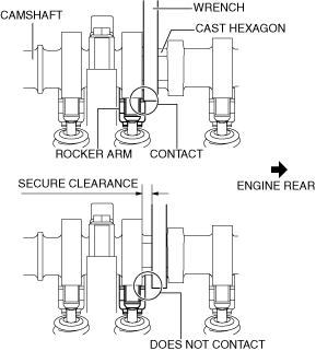
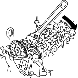
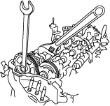
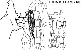
• When rotating the camshaft using a wrench on the cast hexagon, the wrench may contact the rocker arm and damage the rocker arm. To prevent damage to the rocker arm when holding the camshaft on the cast hexagon, use a wrench on the rear side of the engine as shown in the figure to secure a clearance between the cam.
-
Note
-
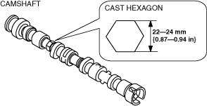
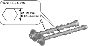
• Width at the cast hexagon of the camshaft is
22—24 mm {0.87—0.94 in}.
Fuel injector (2pin type)
Fuel injector (6pin type)
1. Disconnect the negative battery terminal. (See NEGATIVE BATTERY TERMINAL DISCONNECTION/CONNECTION.)
2. Remove the engine cover. (See ENGINE COVER REMOVAL/INSTALLATION [SKYACTIV-D 2.2].)
3. Remove the fuel injectors. (See FUEL INJECTOR REMOVAL/INSTALLATION [SKYACTIV-D 2.2].)
4. Remove the lower case. (See LOWER CASE REMOVAL/INSTALLATION [SKYACTIV-D 2.2].)
5. Remove the vacuum pump. (See VACUUM PUMP REMOVAL/INSTALLATION [SKYACTIV-D 2.2].)
6. Remove the supply pump. (See SUPPLY PUMP REMOVAL/INSTALLATION [SKYACTIV-D 2.2].)
7. Remove the cylinder head cover. (See TIMING CHAIN REMOVAL/INSTALLATION [SKYACTIV-D 2.2].)
8. Remove the CMP sensor. (See CAMSHAFT POSITION (CMP) SENSOR REMOVAL/INSTALLATION [SKYACTIV-D 2.2].)
9. Remove the front splash shield (RH). (See SPLASH SHIELD REMOVAL/INSTALLATION.)
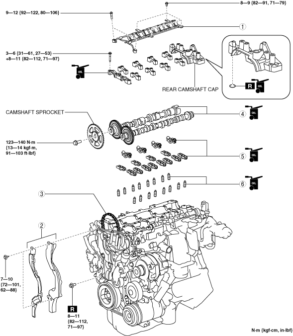
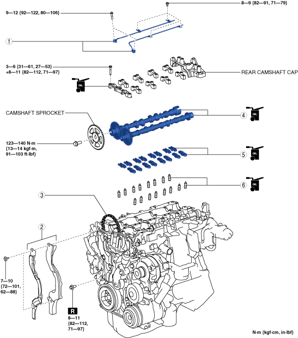
10. Remove in the order indicated in the table.
11. Install in the reverse order of removal.
12. Start the engine and inspect the following:
-
Fuel injector (2pin type)
Fuel injector (6pin type)
|
1
|
Oil shower pipe
|
|
2
|
Noise suppression cover (No.1), seal rubber (No.1)
|
|
3
|
Timing chain
|
|
4
|
Camshaft
|
|
5
|
Rocker arm
|
|
6
|
HLA
|
Noise Suppression Cover (No.1), Seal Rubber (No.1) Removal Note
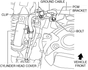
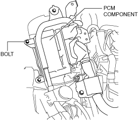
1. Remove the clip and bolt shown in the figure and set the ground cable aside.
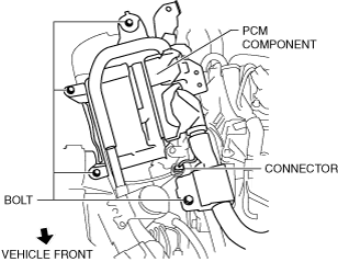
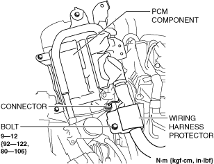
2. Remove the bolts and connector shown in the figure and set the PCM component aside with the PCM connector connected.
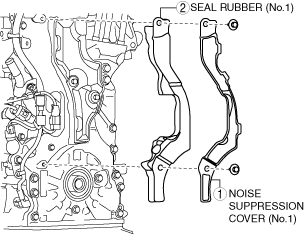
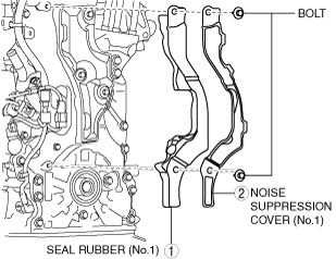
3. Remove the noise suppression cover (No.1) and seal rubber (No.1) in the order shown in the figure.
Timing Chain Removal Note
-
Caution
-
• Keep the timing chain and camshaft sprocket pulled up during and after the work in which it has been set aside from the exhaust camshaft. If the chain falls down, it may disengage from the sprocket on the crankshaft side and deviate, leading to valve timing deviation.
• After servicing, always verify the valve timing.
1. Release the tension on the timing chain using the following procedure:
-
Note
-
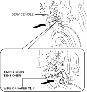
• Release the tension on the timing chain by securing the plunger of the timing chain tensioner through the service hole on the engine front cover.
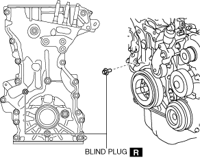
- (1) Remove the blind plug on the engine front cover service hole.
-
- (2) Insert a wire with an approx. diameter of 1.4 mm {0.055 in} or a paper clip into the body hole of the timing chain tensioner through the service hole.
-
-
Note
-
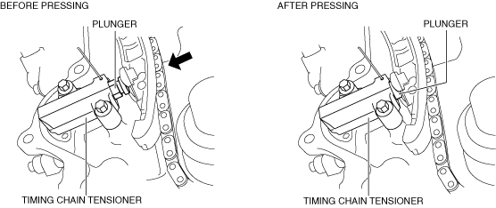
• Before pressing the plunger of the timing chain tensioner, insert the wire or paper clip approx. 22.5 mm {0.886 in} from the engine front cover.
- (3) While moving the exhaust camshaft in the direction of the arrow using a wrench on the cast hexagon, press on the plunger of the timing chain tensioner.
-
-
Note
-
• By rotating the exhaust camshaft clockwise, the timing chain can be pulled slightly and the timing chain presses in the tensioner plunger.
- (4) Press on the wire set in Step 2 or paper clip further with the plunger pressed.
-
-
Note
-
• While the plunger of the timing chain tensioner is pressed, the wire or paper clip can be inserted further to approx. 8 mm {0.3 in}.
• The wire or paper clip secures the plunger, and the tension can be released.
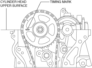
2. Rotate the crankshaft clockwise so that cylinder No.1 is positioned at top dead center (TDC) as shown in the figure.
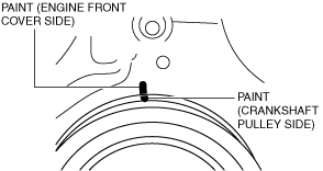
3. Place a paint mark on the engine front cover and crankshaft pulley so that the valve timing can be verified when assembling.
-
Note
-
• The position in while the paint mark is placed is not restricted. The marked position is fine as long as visual verification is possible after assembly.
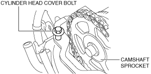
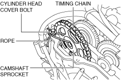
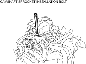
4. Temporarily install the cylinder head cover bolt to the position shown in the figure to use it for suspending the timing chain and camshaft sprocket.
5. Hold the exhaust camshaft using a wrench on the cast hexagon and remove the camshaft sprocket installation bolt.
6. Separate the camshaft sprocket and the exhaust camshaft while the timing chain is hung on the camshaft sprocket.
7. Pull up the camshaft sprocket using a rope while the timing chain is hung on the camshaft sprocket and pulled it up as shown in the figure.
Camshaft Removal Note
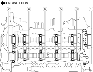
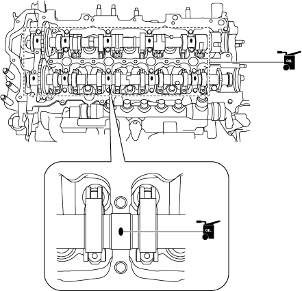
1. Loosen the camshaft cap bolts in two or three passes in the order shown in the figure, and remove the camshaft caps.
2. Remove the camshafts.
Rocker Arm Removal Note
1. Keep the rocker arms in the order of removal to enable reassembly in their original positions.
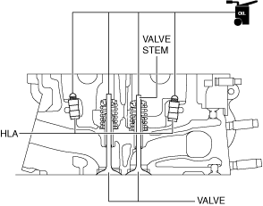
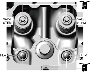
HLA Removal Note
1. Keep the HLAs in the order of removal to enable reassembly in their original positions.
HLA Installation Note
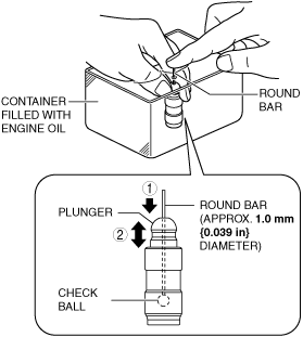
1. Perform HLA air bleeding using the following procedure.
- (1) Put the HLA in a container filled with engine oil.
-
-
Caution
-
• Do not insert the round bar firmly because the check ball spring force is extremely weak.
- (2) While lightly pressing the check ball using a round bar (approx. 1.0 mm {0.039 in} diameter), bleed air by moving the plunger up and down.
-
- (3) Press the end of the plunger in the oil and verify that there is no rebounding feel.
-
-
• If rebounding feel cannot be eliminated, replace the HLA.
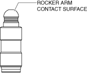
2. Visually inspect the HLA surface where it contacts the rocker arm for wear or damage.
-
• If there is any malfunction, replace the HLA.
3. Assemble the HLAs to their original positions.
Rocker Arm Installation Note
1. Apply engine oil to the HLAs and the end of the valve stems.
Fuel injector (2pin type)
Fuel injector (6pin type)
2. Install the rocker arms to the same positions as before removal.
Camshaft Installation Note
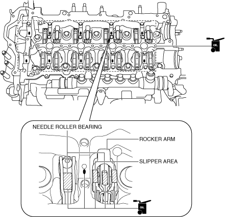
1. Apply gear oil (SAE 90 or equivalent) or engine oil to the following locations.
-
• Each journal of the cylinder head
• Needle roller bearing and slipper area of the rocker arm
Fuel injector (2pin type)
Fuel injector (6pin type)
2. Apply gear oil (SAE 90 or equivalent) or engine oil to the following locations of each camshaft.
-
• Gear sliding surfaces
• Thrust surface of front journal
-
Note
-
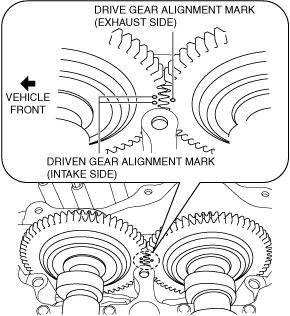
• If oil is applied to the front camshaft cap, oil should not be applied to the thrust surface of the front journal.
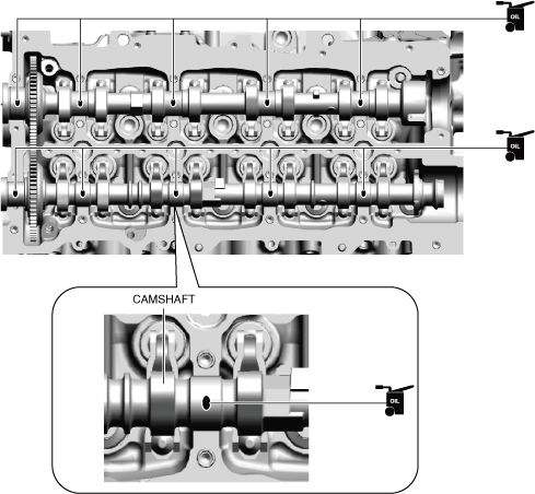
3. Place the camshaft on the cylinder head and align the alignment marks for each gear as shown in the figure.
4. As shown in the figure, apply gear oil (SAE 90 or equivalent) or engine oil to the center area of each journal of the camshaft.
Fuel injector (2pin type)
Fuel injector (6pin type)
-
Caution
-
• Do not spill sealant agent on the journal.
• To prevent sealant agent from hardening, adhere the rear camshaft cap to the cylinder head within 10 min after sealant agent is applied. Tighten the installation bolts completely soon after adhering.
5. Apply sealant agent (Loctite #962T or equivalent) to the rear side of the cylinder head or rear camshaft cap.
-
Note
-
• The permissible range of sealant protrusion is within the shaded areas shown in the figure.
• To prevent engine oil leakage, seal the journal by applying sealant to the rear side of the cylinder head or rear camshaft cap.
Fuel injector (2pin type)
Fuel injector (6pin type)
-
Sealant agent bead width
-
Fuel injector (2pin type) : 1—3 mm {0.04—0.11 in}
Fuel injector (6pin type) : 0.5mm {0.02 in} or more
-
Caution
-
• Be careful not to damage or drop the O-ring when installing the rear camshaft cap.
6. Apply engine oil to the new rear camshaft cap O-ring and install it to the rear camshaft cap.
7. Apply gear oil (SAE 90 or equivalent) or engine oil to the thrust surface of the front camshaft cap.
-
Note
-
• If oil is applied to the front journal thrust surface of each camshaft, oil should not be applied to the front camshaft cap.
8. Install the camshaft caps in the marked number order, and temporarily tighten the camshaft cap installation bolts in two or three passes evenly.
9. Tighten the camshaft cap installation bolts in two steps in the order shown in the figure.
-
Tightening torque
-
Step 1: 3.0—6.0 N·m {31—61 kgf·cm, 27—53 in·lbf}
Step 2: 8—11 N·m {82—112 kgf·cm, 71—97 in·lbf}
Timing Chain Installation Note
1. Pull the timing chain and the camshaft sprocket and remove the suspending rope.
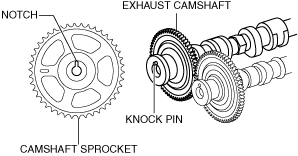
2. Align the knock pin on the end of the exhaust camshaft with the notch on the camshaft sprocket side, then assemble the sprocket.
-
Note
-
• Align the knock pin and the notch while adjusting the knock pin position by rotating the camshaft.
3. Tighten the camshaft sprocket installation bolt using the following procedure:
- (1) Temporarily tighten the camshaft sprocket installation bolt.
-
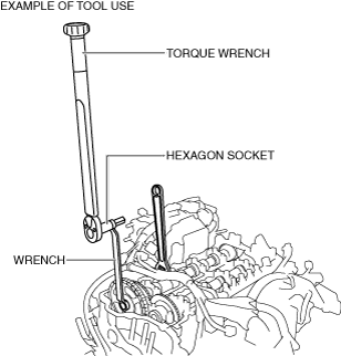
- (2) Hold the exhaust camshaft using a wrench on the cast hexagon, and tighten the camshaft sprocket installation bolt.
-
-
Tightening torque
-
123—140 N·m {13—14 kgf·m, 91—103 ft·lbf}
-
Note
-
• If there is no appropriate tool which can be used to tighten the camshaft sprocket installation bolt to the specified tightening torque, tighten the bolt using the method as shown in the figure. For the specified tightening torque calculation method if the tool is elongated, refer to the “SERVICE CAUTIONS” in the general information. (See
SERVICE CAUTIONS.)
4. Remove the wire or paper clip securing the plunger of the timing chain tensioner and apply tension to the timing chain.
5. Rotate the crankshaft clockwise twice and verify that the valve timing is correct.
-
6. Remove the temporarily assembled cylinder head cover bolt.
7. Install the new blind plug for the engine front cover service hole.
-
Tightening torque
-
8—11 N·m {82—112 kgf·cm, 71—97 in·lbf}
Noise Suppression Cover (No.1), Seal Rubber (No.1) Installation Note
-
Caution
-
• Be careful that the cover and seal rubber do not get hang up on the noise suppression cover installation bolts.
1. Install the noise suppression cover (No.1) and seal rubber (No.1) in the order shown in the figure.
-
Tightening torque
-
7—10 N·m {72—101 kgf·cm, 62—88 in·lbf}
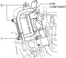
2. Install the PCM component using the following procedure:
- (1) Install the wiring harness protector and connector.
-
- (2) Temporarily tighten the bolt shown in the figure.
-
- (3) Tighten the PCM component installation bolts in the order shown in the figure.
-
-
Tightening torque
-
9—10 N·m {92—101 kgf·cm, 80—88 in·lbf}
3. Install the ground cable to the PCM bracket.
-
Tightening torque
-
9—12 N·m {92—122 kgf·cm, 80—106 in·lbf}
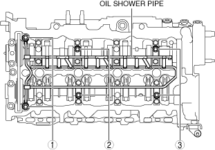
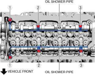
Oil Shower Pipe Installation Note
1. Install the oil shower pipe in the order shown in the figure.
Fuel injector (2pin type)
Fuel injector (6pin type)
Tightening torque
|
Installation position
|
Tightening torque
|
|
1
|
9—12 N·m {92—122 kgf·cm, 80—106 in·lbf}
|
|
2, 3
|
8.0—9.0 N·m {82—91 kgf·cm, 71—79 in·lbf}
|