HIGH PRESSURE FUEL PUMP REMOVAL/INSTALLATION [WITHOUT CYLINDER DEACTIVATION (SKYACTIV-G 2.0, SKYACTIV-G 2.5)]
id0114m1801400
Replacement Part
|
High pressure fuel pipe
Quantity: 1
Location of use: High pressure fuel pump
|
Seal rubber
Quantity: 1
Location of use: High pressure fuel pump
|
O-ring
Quantity: 1
Location of use: High pressure fuel pump
|
|
Gasket
Quantity: 1
Location of use: Rear housing
|
—
|
—
|
Oil and Chemical Type
|
Engine oil
Type: Recommended oil
|
Silicone sealant
Type: TB1217D or equlvalent
|
-
Warning
-
• Highly pressurized fuel may spray out if the fuel line is cut. Due to the following dangers occurring with a fuel spray, always complete the “Fuel Line Safety Procedure” to prevent the fuel from spraying.
-
― Fuel may cause irritation if it comes in contact with skin and eyes.
― If fuel ignites and causes a fire, it may lead to serious injury or death, and damage to property and facilities.
• A person charged with static electricity could cause a fire or explosion, resulting in death or serious injury. Before performing work on the fuel system, discharge static electricity by touching the vehicle body.
-
Caution
-
• Do not disassemble the high pressure fuel pump.
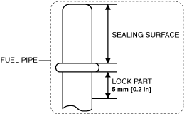
• Do not damage the sealing surface or the lock part of the fuel pipe.
• Damage or deformation to the end of the high pressure line pipe may cause fuel leakage.
• Disconnecting/connecting the quick release connector without cleaning it may cause damage to the fuel pipe and quick release connector. Always clean the quick release connector joint area before disconnecting/connecting using a cloth or soft brush, and make sure that it is free of foreign material.
1. Complete the “BEFORE SERVICE PRECAUTION”. (See BEFORE SERVICE PRECAUTION [WITHOUT CYLINDER DEACTIVATION (SKYACTIV-G 2.0, SKYACTIV-G 2.5)].)
2. Disconnect the negative battery terminal. (See NEGATIVE BATTERY TERMINAL DISCONNECTION/CONNECTION.)
3. Remove the plug hole plate. (See PLUG HOLE PLATE REMOVAL/INSTALLATION [WITHOUT CYLINDER DEACTIVATION (SKYACTIV-G 2.0, SKYACTIV-G 2.5)].)
4. Remove the air cleaner and air hose as a single unit. (See INTAKE-AIR SYSTEM REMOVAL/INSTALLATION [WITHOUT CYLINDER DEACTIVATION (SKYACTIV-G 2.0, SKYACTIV-G 2.5)].)
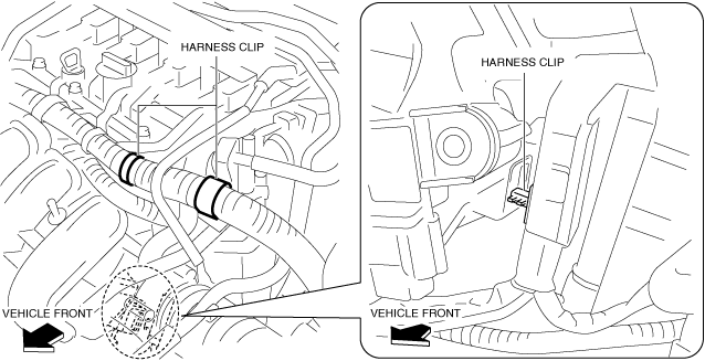
5. Disconnect the harness clip as shown in the figure.
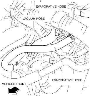
6. Disconnect the hoses as shown in the figure.
7. Disconnect the following parts connectors.
-
• Purge solenoid valve
• High pressure fuel pump
• Intake CMP sensor
• Coolant control valve (With coolant control valve)
8. Remove the purge solenoid valve and catch tank and purge solenoid valve bracket as a single unit. (See PURGE SOLENOID VALVE REMOVAL/INSTALLATION [WITHOUT CYLINDER DEACTIVATION (SKYACTIV-G 2.0, SKYACTIV-G 2.5)].)
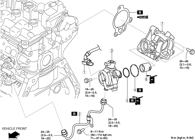
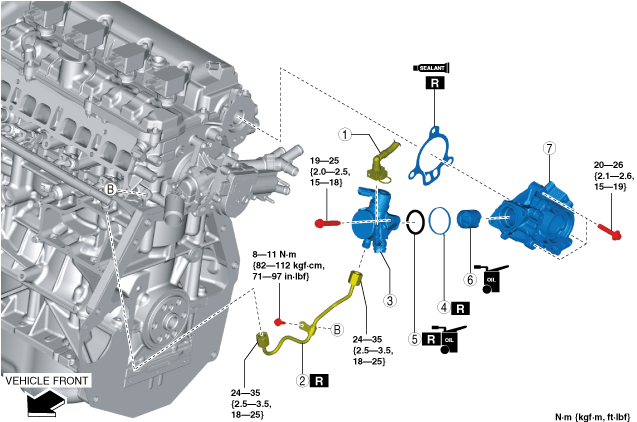
9. Remove in the order indicated in the table.
-
Note
-
• Only when the high pressure fuel pump (figure (4)) is removed, the rear housing (figure (8)) does not have to be removed.
10. Install in the reverse order of removal.
11. Complete the “AFTER SERVICE PRECAUTION”. (See AFTER SERVICE PRECAUTION [WITHOUT CYLINDER DEACTIVATION (SKYACTIV-G 2.0, SKYACTIV-G 2.5)].)
12. Complete the “Fuel Leakage Inspection After High Pressure Fuel Pump Installation”. (See Fuel Leakage Inspection After High Pressure Fuel Pump Installation.)
Without coolant control valve
|
1
|
Quick release connector
|
|
2
|
High pressure fuel pipe
|
|
3
|
High pressure fuel pump
|
|
4
|
Seal rubber
|
|
5
|
O-ring
|
|
6
|
Tension collar
|
|
7
|
Rear housing
|
With coolant control valve
|
1
|
Quick release connector
|
|
2
|
High pressure fuel pipe
|
|
3
|
High pressure fuel pump
|
|
4
|
Seal rubber
|
|
5
|
O-ring
|
|
6
|
Tension collar
|
|
7
|
Rear housing
|
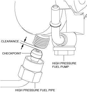
High Pressure Fuel Pipe Removal Note
-
Caution
-
• When removing the high pressure fuel pipe, the end of the high pressure fuel pipe may be damaged because the clearance between the high pressure fuel pump and the high pressure fuel pipe is small. Be very careful when handling the end of the high pressure fuel pipe so as not to damage it.
• If the high pressure fuel pump is removed with the high pressure fuel pipe installed, the high pressure fuel pipe and fuel distributor may be damaged because of the excessive force caused by the spring force of the high pressure fuel pump. The high pressure fuel pipe and fuel distributor must be replaced if they are damaged. Always remove the high pressure fuel pipe before removing the high pressure fuel pump.
1. Remove the high pressure fuel pipe.
Rear Housing Removal Note (Without coolant control valve)
1. Remove the vacuum pump. (See VACUUM PUMP REMOVAL/INSTALLATION [WITHOUT CYLINDER DEACTIVATION (SKYACTIV-G 2.0, SKYACTIV-G 2.5)].)
2. Remove the rear housing.
Rear Housing Removal Note (With coolant control valve)
1. Remove the vacuum pump. (See VACUUM PUMP REMOVAL/INSTALLATION [WITHOUT CYLINDER DEACTIVATION (SKYACTIV-G 2.0, SKYACTIV-G 2.5)].)
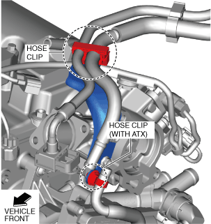
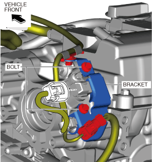
2. Disconnect the hose clips shown in the figure.
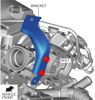
3. Remove the bracket shown in the figure.
4. Disconnect the exhaust CMP sensor connector.
5. Remove the bolts shown in the figure and set the bracket aside so that it does not interfere with the servicing.
6. Remove the rear housing.
Rear Housing Installation Note (Without coolant control valve)
-
Note
-
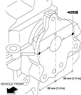
• After applying silicone sealant (TB1217D or equlvalent), install the rear housing within 10 min. and then tighten all bolts within 5 min.
1. Apply silicone sealant (TB1217D or equlvalent) to the areas shown in the figure.
-
Thickness
-
3.0—7.0 mm {0.12—0.27 in}
2. Install the rear housing.
Rear Housing Installation Note (With coolant control valve)
-
Note
-
• After applying silicone sealant (TB1217D or equivalent), install the rear housing within 10 min. and then tighten all bolts within 5 min.
1. Apply silicone sealant (TB1217D or equivalent) to the areas shown in the figure.
-
Thickness
-
3.0—7.0 mm {0.12—0.27 in}
2. Install the rear housing.
3. Install the bracket shown in the figure.
-
Tightening torque
-
8—11 N·m {82—112 kgf·cm, 71—97 in·lbf}
4. Connect the exhaust CMP sensor connector.
5. Install the bracket shown in the figure.
-
Tightening torque
-
8—10 N·m {82—101 kgf·cm, 71—88 in·lbf}
6. Connect the hose clips shown in the figure.
7. Install the vacuum pump. (See VACUUM PUMP REMOVAL/INSTALLATION [WITHOUT CYLINDER DEACTIVATION (SKYACTIV-G 2.0, SKYACTIV-G 2.5)].)
High Pressure Fuel Pump Installation Note
1. Rotate the crankshaft clockwise from TDC (position shown in figure) of cylinder No.1.
Without Coolant Control Valve
With Coolant Control Valve
2. Insert the high pressure fuel pump into the rear housing.
3. Press in the high pressure fuel pump until the O-ring cannot be seen.
4. Temporarily tighten the high pressure fuel pump installation bolt on one side until its head contacts the high pressure fuel pump.
5. Tighten the high pressure fuel pump installation bolt which is not tightened in Step 5.
-
High pressure fuel pump installation bolt tightening torque
-
19—25 N·m {2.0—2.5 kgf·m, 15—18 ft·lbf}
6. Tighten the high pressure fuel pump installation bolt which was tightened in Step 5.
-
High pressure fuel pump installation bolt tightening torque
-
19—25 N·m {2.0—2.5 kgf·m, 15—18 ft·lbf}
High Pressure Fuel Pipe Installation Note
-
Caution
-
• Damage or deformation to the end of the high pressure fuel pipe may cause fuel leakage. When installing the high pressure fuel pipe to the high pressure fuel pump, be very careful while handling the end of the high pressure fuel pipe.
• If parts are exposed to fuel, their function may be decreased or a fire may occur. Always wipe off any leaked fuel using a clean rag.
• Do not let foreign materials enter into the high pressure fuel pipe.
• Install a new high pressure fuel pipe because it cannot be reused.
1. Temporarily tighten the nuts on both ends.
2. Temporarily tighten the high pressure fuel pipe bracket installation bolt.
3. Tighten the nuts on both ends.
-
High pressure fuel pipe tightening torque
-
24—35 N·m {2.5—3.5 kgf·m, 18—25 ft·lbf}
4. Tighten the high pressure fuel pipe bracket installation bolt.
-
High pressure fuel pipe bracket installation bolt tightening torque
-
8—11 N·m {82—112 kgf·cm, 71—97 in·lbf}
Fuel Leakage Inspection After High Pressure Fuel Pump Installation
1. Verify that the high pressure fuel pump is assembled securely.
2. Verify that there is no fuel leakage around the high pressure fuel pump.