DTC C0031:11/C0031:15/C0034:11/C0034:15/C0037:11/C0037:15/C003A:11/C003A:15 [DYNAMIC STABILITY CONTROL (DSC)]


id0402b2180700

DTC
C0031:11, C0031:15
ABS wheel-speed sensor (LF)
C0034:11, C0034:15
ABS wheel-speed sensor (RF)
C0037:11, C0037:15
ABS wheel-speed sensor (LR)
C003A:11, C003A:15
ABS wheel-speed sensor (RR)
DETECTION CONDITION
•  C0031:11, C0034:11, C0037:11, C003A:11
―  Short to ground has been detected in the ABS wheel-speed sensor wiring harness on any of the four vehicle wheels.
•  C0031:15, C0034:15, C0037:15, C003A:15
―  Open circuit or short to power supply has been detected in the ABS wheel-speed sensor wiring harness on any of the four vehicle wheels.
FAIL-SAFE FUNCTION
Refer to “DTC Table” and “Fail-safe function table”. (See DTC TABLE [DYNAMIC STABILITY CONTROL (DSC)].)
POSSIBLE CAUSE
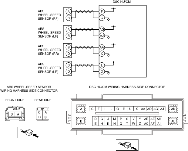
•  Open circuit or short to ground/power supply in the wiring harness between the following DSC HU/CM terminals and ABS wheel-speed sensor terminals:
―  DSC HU/CM terminal F—ABS wheel-speed sensor (RF) terminal A
―  DSC HU/CM terminal C—ABS wheel-speed sensor (RF) terminal B
―  DSC HU/CM terminal AG—ABS wheel-speed sensor (LF) terminal A
―  DSC HU/CM terminal AJ—ABS wheel-speed sensor (LF) terminal B
―  DSC HU/CM terminal AA—ABS wheel-speed sensor (RR) terminal B
―  DSC HU/CM terminal X—ABS wheel-speed sensor (RR) terminal D
―  DSC HU/CM terminal L—ABS wheel-speed sensor (LR) terminal B
―  DSC HU/CM terminal O—ABS wheel-speed sensor (LR) terminal D
•  Malfunction in the ABS wheel-speed sensor
•  DSC HU/CM malfunction
•  Poor connection at connectors (female terminal)

Diagnostic procedure

STEP

INSPECTION

ACTION

1
INSPECT ABS WHEEL-SPEED SENSOR FOR SHORT TO GROUND
•  Switch the ignition to off.
•  Disconnect the DSC HU/CM connectors.
•  Inspect for continuity between the following DSC HU/CM connector terminals (vehicle harness-side) and body ground:
―  ABS wheel-speed sensor (RF) (+): F
―  ABS wheel-speed sensor (RF) (-): C
―  ABS wheel-speed sensor (LF) (+): AG
―  ABS wheel-speed sensor (LF) (-): AJ
―  ABS wheel-speed sensor (RR) (+): AA
―  ABS wheel-speed sensor (RR) (-): X
―  ABS wheel-speed sensor (LR) (+): L
―  ABS wheel-speed sensor (LR) (-): O
•  Is there continuity?
Yes
Go to the next step.
No
Go to Step 3.
2
INSPECT ABS WHEEL-SPEED SENSOR WIRING HARNESS FOR SHORT TO GROUND
•  Disconnect the ABS wheel-speed sensor connectors.
•  Inspect for continuity between the following DSC HU/CM connector terminals (vehicle harness-side) and body ground:
―  ABS wheel-speed sensor (RF) (+): F
―  ABS wheel-speed sensor (RF) (-): C
―  ABS wheel-speed sensor (LF) (+): AG
―  ABS wheel-speed sensor (LF) (-): AJ
―  ABS wheel-speed sensor (RR) (+): AA
―  ABS wheel-speed sensor (RR) (-): X
―  ABS wheel-speed sensor (LR) (+): L
―  ABS wheel-speed sensor (LR) (-): O
•  Is there continuity?
Yes
Repair or replace the wiring harness, then go to Step 5.
No
Replace the ABS wheel-speed sensor, then go to Step 5.
3
INSPECT FOR OPEN CIRCUIT IN ABS WHEEL-SPEED SENSOR WIRING HARNESS
•  Inspect for continuity between the DSC HU/CM connectors (vehicle harness-side) and the following vehicle harness-side connector terminals of the ABS wheel-speed sensors:
―  ABS wheel-speed sensor (RF) (+): F—A
―  ABS wheel-speed sensor (RF) (-): C—B
―  ABS wheel-speed sensor (LF) (+): AG—A
―  ABS wheel-speed sensor (LF) (-): AJ—B
―  ABS wheel-speed sensor (RR) (+): AA—B
―  ABS wheel-speed sensor (RR) (-): X—D
―  ABS wheel-speed sensor (LR) (+): L—B
―  ABS wheel-speed sensor (LR) (-): O—D
•  Is there continuity?
Yes
Go to the next step.
No
Repair or replace the wiring harness, then go to the next step.
4
INSPECT ABS WHEEL-SPEED SENSOR WIRING HARNESS FOR SHORT TO POWER SUPPLY
•  Inspect for voltage between the following DSC HU/CM connector terminals (vehicle harness-side) and body ground:
―  ABS wheel-speed sensor (RF) (+): F
―  ABS wheel-speed sensor (RF) (-): C
―  ABS wheel-speed sensor (LF) (+): AG
―  ABS wheel-speed sensor (LF) (-): AJ
―  ABS wheel-speed sensor (RR) (+): AA
―  ABS wheel-speed sensor (RR) (-): X
―  ABS wheel-speed sensor (LR) (+): L
―  ABS wheel-speed sensor (LR) (-): O
•  Is the voltage 1 V or less?
Yes
Go to the next step.
No
Repair or replace the wiring harness, then go to the next step.
5
VERIFY THAT THE SAME DTC IS NOT PRESENT
•  Reconnect all disconnected connectors.
•  Clear the DTCs from the memory.
•  Are the same DTCs present?
Yes
Repeat the inspection from Step 1.
If the malfunction recurs, replace the DSC HU/CM, then go to the next step.
No
Go to the next step.
6
VERIFY THAT NO OTHER DTCS ARE PRESENT
•  Are any other DTCs output?
Yes
Go to the applicable DTC inspection.
No
DTC troubleshooting completed.