DTC C0023:62/C0040:64 [DYNAMIC STABILITY CONTROL (DSC)]
id0402b2906400
DTC
|
C0023:62, C0040:64
|
Brake switch
|
|
DETECTION CONDITION
|
• C0023:62
• C0040:64
|
||
FAIL-SAFE FUNCTION
|
Refer to “DTC Table” and “Fail-safe function table”. (See DTC TABLE [DYNAMIC STABILITY CONTROL (DSC)].)
|
||
POSSIBLE CAUSE
|
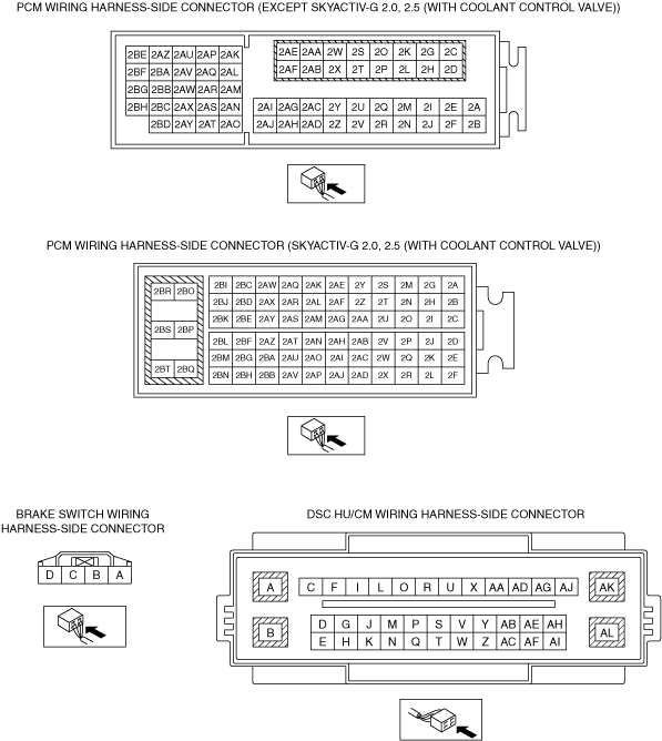
• Open or short circuit in wiring harness between the brake switch and PCM terminal 2G (SKYACTIV-G 2.0, 2.5 (without coolant control valve) and SKYACTIV-G 2.5T)
• Open or short circuit in wiring harness between the brake switch and PCM terminal 2AB (SKYACTIV-G 2.0, 2.5 (with coolant control valve))
• Open or short circuit in wiring harness between the brake switch and PCM terminal 2AA (SKYACTIV-D 2.2 (FUEL INJECTOR (2PIN TYPE))
• Open or short circuit in wiring harness between the brake switch and PCM terminal 2U (SKYACTIV-D 2.2 (FUEL INJECTOR (6PIN TYPE))
• Brake switch malfunction
• PCM malfunction
• Rear body control module (RBCM) and/or brake light relay malfunction
• DSC HU/CM malfunction
• Poor connection at connectors (female terminal)
|
||
![]() |
|||
![]() |
Diagnostic procedure
STEP |
INSPECTION |
ACTION |
|
---|---|---|---|
1
|
VERIFY OPEN OR SHORT CIRCUIT IN BRAKE SWITCH SIGNAL
• Switch the ignition ON (engine off).
• Measure the voltage between the PCM connector terminal 2G (SKYACTIV-G 2.0, 2.5 (without coolant control valve) and SKYACTIV-G 2.5T)/2AB (SKYACTIV-G 2.0, 2.5 (with coolant control valve))/2AA (SKYACTIV-D 2.2 (FUEL INJECTOR (2PIN TYPE))/2U (SKYACTIV-D 2.2 (FUEL INJECTOR (6PIN TYPE)) (vehicle harness-side) and body ground when the brake pedal is depressed and released.
• Is the voltage normal?
|
Yes
|
Go to Step 5.
|
No
|
If it is B+ under any condition, then go to the next step.
If it is 1 V or less under any condition, then go to Step 3.
|
||
2
|
INSPECT BRAKE SWITCH SIGNAL FOR SHORT TO POWER SUPPLY CIRCUIT
• Disconnect the brake switch connector.
• Measure voltage between the brake switch connector terminal D (vehicle harness-side) and body ground.
• Is the voltage 1 V or less?
|
Yes
|
Go to Step 4.
|
No
|
Repair or replace the wiring harness between the PCM and brake switch, then go to Step 7
|
||
3
|
INSPECT BRAKE SWITCH SIGNAL FOR OPEN CIRCUIT
• Disconnect the PCM connectors.
• Disconnect the brake switch connector.
• Inspect continuity between the PCM and brake switch as follows.
• Is there continuity?
|
Yes
|
Go to the next step.
|
No
|
Repair or replace the wiring harness between the PCM and brake switch, then go to Step 7.
|
||
4
|
INSPECT BRAKE SWITCH
• Inspect the brake switch.
(See BRAKE SWITCH INSPECTION.)
• Is the brake switch normal?
|
Yes
|
Go to the next step.
|
No
|
Replace the brake switch, then go to the next step.
|
||
5
|
PERFORM REAR BODY CONTROL MODULE (RBCM) DTC INSPECTION
• Reconnect all disconnected connectors.
• Using the M-MDS, perform the DTC inspection for the rear body control module (RBCM).
• Are any DTCs detected?
|
Yes
|
Go to applicable DTC inspection.
|
No
|
Go to the next step.
|
||
6
|
PERFORM PCM DTC INSPECTION
• Using the M-MDS, perform the DTC inspection for the PCM.
• Are any DTCs detected?
|
Yes
|
Go to applicable DTC inspection.
|
No
|
Go to the next step.
|
||
7
|
VERIFY THAT THE SAME DTC IS NOT PRESENT
• Reconnect all disconnected connectors.
• Clear the DTCs from the memory.
• Start the engine and drive the vehicle at 20 km/h {12 mph} or more.
• Are the same DTCs present?
|
Yes
|
Repeat the inspection from Step 1.
If the malfunction recurs, replace the DSC HU/CM, then go to the next step.
|
No
|
Go to the next step.
|
||
8
|
VERIFY THAT NO OTHER DTCS ARE PRESENT
• Are any other DTCs output?
|
Yes
|
Go to the applicable DTC inspection.
|
No
|
DTC troubleshooting completed.
|