 |
ac5wzw00009812
POWER BRAKE UNIT REMOVAL/INSTALLATION [R.H.D.]
id041100801852
Replacement Part
|
Pipe holder
Quantity: 1
Location of use: Brake pipe
|
Gasket
Quantity: 1
Location of use: Power brake unit
|
Brake switch
Quantity: 1
Location of use: Brake pedal
|
Oil and Chemical Type
|
Brake fluid type
Type: SAE J1703 or FMVSS116 DOT-3 or DOT-4
|
1. Disconnect the negative battery terminal. (See NEGATIVE BATTERY TERMINAL DISCONNECTION/CONNECTION.)
2. Remove the following parts:
3. Remove the master cylinder. (See MASTER CYLINDER REMOVAL/INSTALLATION [R.H.D.].)
4. Remove the power brake unit vacuum sensor. (With i-stop) (See POWER BRAKE UNIT VACUUM SENSOR REMOVAL/INSTALLATION [R.H.D.].)
5. Remove the washer tank bracket. (See WASHER TANK REMOVAL/INSTALLATION.)
6. For SKYACTIV-D 2.2 or SKYACTIV-G 2.5T vehicles, remove front under cover No.2. (See FRONT UNDER COVER No.2 REMOVAL/INSTALLATION.)
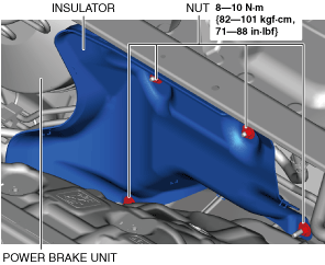
7. Remove the insulator.
ac5wzw00009812
|
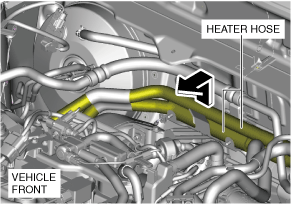
8. Set the heater hoses out of the way as shown in the figure. (SKYACTIV-G 2.5T)
ac5wzw00013258
|
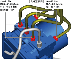
9. Disconnect the brake pipe from the DSC HU/CM.
ac5wzw00009813
|
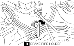
10. Disconnect the brake pipe holder from the vehicle.
ac5wzw00012849
|
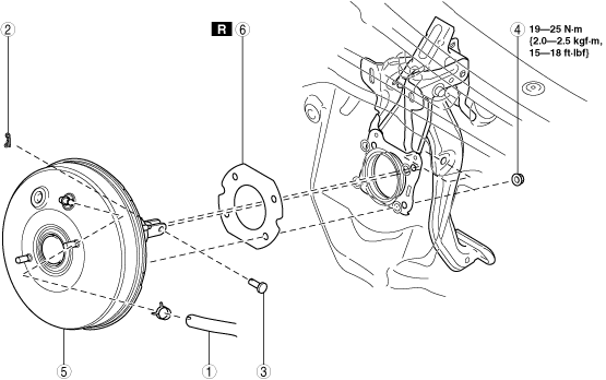
11. Remove in the order indicated in the table.
12. Install in the reverse order of removal.
13. After installation, add brake fluid, bleed the air, and inspect for fluid leakage. (See BRAKE FLUID AIR BLEEDING.)
14. Remove the brake switch. (See BRAKE PEDAL REMOVAL/INSTALLATION [R.H.D.].)
15. Inspect the brake pedal. (See BRAKE PEDAL INSPECTION.)
16. Install a new brake switch. (See BRAKE PEDAL REMOVAL/INSTALLATION [R.H.D.].)
ac5wzw00009815
|
|
1
|
Vacuum hose
|
|
2
|
Snap pin
|
|
3
|
Clevis pin
|
|
4
|
Nut
|
|
5
|
Power brake unit
|
|
6
|
Gasket
|