 |
ac5uuw00005814
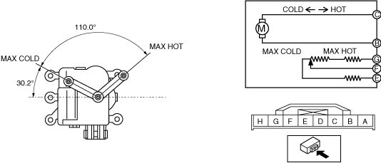
AIR MIX ACTUATOR INSPECTION [FULL-AUTO AIR CONDITIONER]
id0740a1802500
L.H.D.
Driver-side
1. Disconnect the negative battery terminal. (See NEGATIVE BATTERY TERMINAL DISCONNECTION/CONNECTION.)
2. Remove the following parts:
3. Remove the driver-side air mix actuator. (See AIR MIX ACTUATOR REMOVAL/INSTALLATION [FULL-AUTO AIR CONDITIONER].)
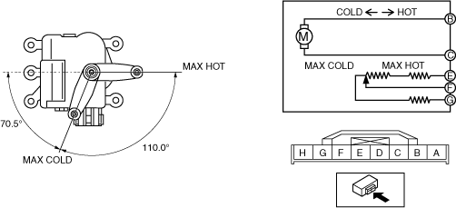
4. Apply battery positive voltage and connect the ground to the air mix actuator terminals as indicated in the table below and verify the operation condition.
|
Terminal |
Air mix actuator operation |
|
|---|---|---|
|
B |
C |
|
|
B+
|
Ground
|
COLD → HOT
|
|
Ground
|
B+
|
HOT → COLD
|
ac5uuw00005814
|
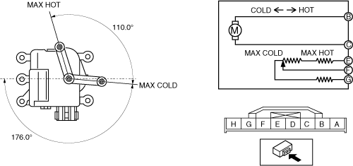
5. Verify that the resistance between terminals F and G, E and F matches the air mix actuator operation as shown in the graph.
ac5wzw00010423
|
Passenger-side
1. Disconnect the negative battery terminal. (See NEGATIVE BATTERY TERMINAL DISCONNECTION/CONNECTION.)
2. Remove the following parts:
3. Remove the passenger-side air mix actuator. (See AIR MIX ACTUATOR REMOVAL/INSTALLATION [FULL-AUTO AIR CONDITIONER].)
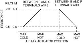
4. Apply battery positive voltage and connect the ground to the air mix actuator terminals as indicated in the table below and verify the operation condition.
|
Terminal |
Air mix actuator operation |
|
|---|---|---|
|
B |
C |
|
|
B+
|
Ground
|
HOT → COLD
|
|
Ground
|
B+
|
COLD → HOT
|
ac5uuw00005816
|
5. Verify that the resistance between terminals F and G, E and F matches the air mix actuator operation as shown in the graph.
ac5wzw00010424
|
R.H.D.
Driver-side
1. Disconnect the negative battery terminal. (See NEGATIVE BATTERY TERMINAL DISCONNECTION/CONNECTION.)
2. Remove the driver-side air mix actuator. (See AIR MIX ACTUATOR REMOVAL/INSTALLATION [FULL-AUTO AIR CONDITIONER].)
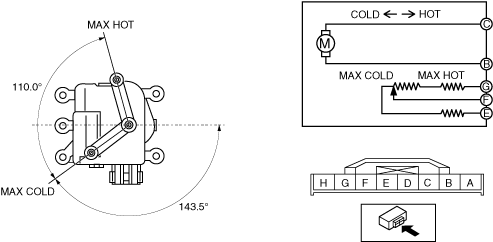
3. Apply battery positive voltage and connect the ground to the air mix actuator terminals as indicated in the table below and verify the operation condition.
|
Terminal |
Air mix actuator operation |
|
|---|---|---|
|
B |
C |
|
|
B+
|
Ground
|
HOT → COLD
|
|
Ground
|
B+
|
COLD → HOT
|
ac5jjw00008827
|
4. Verify that the resistance between terminals F and G, E and F matches the air mix actuator operation as shown in the graph.
ac5wzw00010424
|
Passenger-side
1. Disconnect the negative battery terminal. (See NEGATIVE BATTERY TERMINAL DISCONNECTION/CONNECTION.)
2. Remove the following parts:
3. Remove the passenger-side air mix actuator. (See AIR MIX ACTUATOR REMOVAL/INSTALLATION [FULL-AUTO AIR CONDITIONER].)
4. Apply battery positive voltage and connect the ground to the air mix actuator terminals as indicated in the table below and verify the operation condition.
|
Terminal |
Air mix actuator operation |
|
|---|---|---|
|
B |
C |
|
|
B+
|
Ground
|
COLD → HOT
|
|
Ground
|
B+
|
HOT → COLD
|
ac5jjw00008829
|
5. Verify that the resistance between terminals F and G, E and F matches the air mix actuator operation as shown in the graph.
ac5wzw00010423
|