|
1
|
INSPECT DRIVER-SIDE CRASH ZONE SENSOR
• Switch the ignition off.
• Disconnect the negative battery terminal and wait for 1 min or more.
• Remove the front bumper.
• Verify that the driver-side crash zone sensor is correctly installed.
• Is the driver-side crash zone sensor correctly installed?
|
Yes
|
Go to the next step.
|
|
No
|
Correctly install the driver-side crash zone sensor.
Then go to Step 7.
|
|
2
|
INSPECT DRIVER-SIDE CRASH ZONE SENSOR CONNECTOR
• Disconnect the driver-side crash zone sensor connector.
• Inspect the driver-side crash zone sensor connector (wiring harness-side). (Corrosion, damage, and disconnected pins)
• Is there any malfunction of the driver-side crash zone sensor connector (wiring harness-side)?
|
Yes
|
Replace the malfunction part, then go to step 7.
|
|
No
|
Go to the next step.
|
|
3
|
INSPECT DRIVER-SIDE CRASH ZONE SENSOR CIRCUIT FOR SHORT TO GROUND
• Remove the column cover.
• Disconnect the clock spring connector.
• Remove the glove compartment.
• Disconnect the passenger-side air bag module connectors.
• Disconnect the driver and passenger-side front seat connectors.
• Remove the B-pillar lower trim.
• Disconnect the driver and passenger-side front pre-tensioner seat belt connectors.
• Remove the trunk side trim.
• Disconnect the driver and passenger-side rear pre-tensioner seat belt connectors.
• Disconnect the driver and passenger-side curtain air bag module connectors.
• Disconnect the all SAS control module connectors.
• Inspect for continuity between the following terminals (wiring harness-side) and body ground:
-
― SAS control module terminal 2O
― SAS control module terminal 2Q
-
Note
-
• Inspect for continuity while shaking the wiring harness between the SAS control module and driver-side crash zone sensor.
• Is there continuity?
|
Yes
|
Refer to the wiring diagram and verify whether or not there is a common connector between SAS control module terminal and driver-side crash zone sensor terminal.
If there is a common connector:
• Determine the malfunctioning part by inspecting the common connector and the terminal for corrosion, damage, or pin disconnection, and the common wiring harness for a short to ground.
• Replace the malfunctioning part.
If there is no common connector:
• Replace the wiring harness which has a short to ground.
Go to Step 7.
|
|
No
|
Go to the next step.
|
|
4
|
INSPECT DRIVER-SIDE CRASH ZONE SENSOR CIRCUIT FOR OPEN CIRCUIT
• Driver-side crash zone sensor and SAS control module connectors are disconnected.
• Inspect for continuity between the following terminals (wiring harness-side):
-
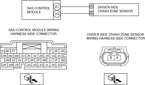
― Driver-side crash zone sensor terminal A—SAS control module terminal 2O
― Driver-side crash zone sensor terminal B—SAS control module terminal 2Q
-
Note
-
• Inspect for continuity while shaking the wiring harness between the SAS control module and driver-side crash zone sensor.
• Is there continuity?
|
Yes
|
Go to the next step.
|
|
No
|
Refer to the wiring diagram and verify whether or not there is a common connector between SAS control module terminal and driver-side crash zone sensor terminal.
If there is a common connector:
• Determine the malfunctioning part by inspecting the common connector and the terminal for corrosion, damage, or pin disconnection, and the common wiring harness for an open circuit.
• Replace the malfunctioning part.
If there is no common connector:
• Replace the wiring harness which has an open circuit.
Go to Step 7.
|
|
5
|
INSPECT DRIVER-SIDE CRASH ZONE SENSOR CIRCUIT FOR SHORT TO OTHER AIR BAG SENSOR CIRCUITS
• Driver-side crash zone sensor and SAS control module connectors are disconnected.
• Disconnect the passenger-side crash zone sensor connector.
• Remove the driver and passenger-side B-pillar lower trim.
• Disconnect the driver and passenger-side side air bag sensor connectors.
• Remove the driver and passenger-side front door trim.
• Disconnect the driver and passenger-side pressure sensor connectors.
• Refer to the wiring diagram and inspect for continuity between the driver-side crash zone sensor terminals and other air bag sensor terminals (wiring harness-side).
-
Note
-
• Inspect for continuity while shaking the wiring harness between the SAS control module and driver-side crash zone sensor.
• Is there continuity?
|
Yes
|
Refer to the wiring diagram and verify whether or not there is a common connector between SAS control module terminal and driver-side crash zone sensor terminal.
If there is a common connector:
• Determine the malfunctioning part by inspecting the common connector and the terminal for corrosion, damage, or pin disconnection, and the common wiring harness for a short to other air bag sensor circuits.
• Replace the malfunctioning part.
If there is no common connector:
• Replace the wiring harness which has a short to other air bag sensor circuits.
Go to Step 7.
|
|
No
|
Go to the next step.
|
|
6
|
INSPECT DRIVER-SIDE CRASH ZONE SENSOR CIRCUIT FOR SHORT TO POWER SUPPLY
• Driver-side crash zone sensor and SAS control module connectors are disconnected.
• Connect the negative battery terminal.
• Switch the ignition ON (engine off or on).
• Measure the voltage at the following terminals (wiring harness-side):
-
― SAS control module terminal 2O
― SAS control module terminal 2Q
-
Note
-
• Measure the voltage while shaking the wiring harness between the SAS control module and driver-side crash zone sensor.
• Is the voltage 0 V?
|
Yes
|
Replace the driver-side crash zone sensor, then go to the next step.
|
|
No
|
Refer to the wiring diagram and verify whether or not there is a common connector between SAS control module terminal and driver-side crash zone sensor terminal.
If there is a common connector:
• Determine the malfunctioning part by inspecting the common connector and the terminal for corrosion, damage, or pin disconnection, and the common wiring harness for a short to power supply.
• Replace the malfunctioning part.
If there is no common connector:
• Replace the wiring harness which has a short to power supply.
Go to the next step.
|
|
7
|
PERFORM SAS CONTROL MODULE DTC INSPECTION
• Switch the ignition off.
• Disconnect the negative battery terminal and wait for 1 min or more.
• Connect the SAS control module connectors.
• Reconnect all disconnected connectors.
• Connect the negative battery terminal.
• Switch the ignition ON (engine off or on).
• Clear the DTC for the SAS control module using the M-MDS.
• Perform the DTC inspection for the SAS control module using the M-MDS.
• Are the same DTCs present?
|
Yes
|
Repeat the inspection from Step 1.
• If the malfunction recurs, replace the SAS control module.
|
|
No
|
DTC troubleshooting completed.
|